ubuntu搭建基于arm-none-eabi-gcc,jlink驱动的平台,并实现stm32f103c8t6程序的编译链接和烧写
ubuntu搭建基于arm-none-eabi-gcc,jlink驱动的环境,并实现stm32f103c8t6程序的编译链接和烧写
说明:
本文内容基于VMware上的ubuntu虚拟机,vmware的版本为15.01,安装的Ubuntu版本为19.0.4。虚拟机的安装很简单,大家可以参考网上的教程安装一下,这里推荐这篇博文:https://blog.csdn.net/zhengyangliu123/article/details/54780835。
个人观点
一直以来博主都是在keil环境下进行的stm32的开发,可谓是深深的被keil之流的IDE给惯坏了,但作为一个有追求的程序员,怎么能甘愿一直呆在IDE的象牙塔里,怎么也得出来看看,了解了解底层是怎么工作的,看看传说中只有架构师才触碰的GCC和makefile到底长啥样。
实际上,整个搭建过程可以让我们从更原始的节点了解stm32的工作过程,更能让我们对软件的工作方式有更深刻的印象。博主经历重重困难才实现了最终的烧录,当程序正常运行时,那一刻别提有多开心了,随即决定写一篇博客纪念一下,也希望能够对广大同行有所帮助。
此文系博主在csdn上的第一篇博客,有什么不周的地方请大家多多担待
主要步骤
1、安装arm-none-eabi-gcc
2、安装jlink驱动
3、更改工程核心文件
4、选择工程启动文件
5、编写链接文件
6、编写工程makefile
7、使用make进行编译链接并生成.bin和.hex文件
8、使用jlink对芯片进行烧录
1、安装arm-none-eabi-gcc
arm-none-eabi-gcc是属于gcc编译工具链,可以理解为针对arm工程的一个编译器,这个编译器只能用来编译裸奔程序,说白了就是不能编译带操作系统的工程,我们可能马上想到是否有能够编译操作系统的工程的版本,由于本博客属于入门级别,所以博主在这不多说太多,感兴趣的可以多了解以下arm-none-eabi-gcc相关系列,这里主要就是基本应用的使用。
它的主要基本功能就是实现编译:把源文件一般是.c文件(还可能是汇编文件,比如stm32工程的启动文件)编译成为.o文件,然后实现链接:把生成的.o文件链接得到目的文件,也就是最终我们要烧录到板子内的.hex或.bin文件。废话不多说,开始安装。
arm-none-eabi-gcc的安装包可以点这里下载:(https://developer.arm.com/open-source/gnu-toolchain/gnu-rm/downloads)

如图,选择合适的版本下载即可(自己的Ubuntu是多少位的尽量就下多少位的,否则后面会有些麻烦,这里博主用的是64位的,32位的可以到这个网站下载,可能都有点慢,国外网站你懂的)。
为便于管理,我们在根目录建立文件夹“STM32_Work_Space”,里面再建立“ARM_NONE_EABI_GCC”文件夹,把压缩包下载到ARM_NONE_EABI_GCC中并解压到当前目录。
我们可以在gcc-arm-none-eabi-8-2019-q3-update文件夹里bin文件夹里看到很多奇怪的文件,实际上这些文件就是用来编译的文件,不同的文件编译的目标不一样。它们都是要在命令行里进行调用,为了方便,我们把bin文件夹路径加到系统环境变量中去,这样我们就不用每次执行都要到这个目录下了,操作如下:
在终端输入:
$ sudo gedit /etc/profile
会打开一个里面写了看似很高级的内容的文本文档,具体是啥意思咱也不懂,反正在最后一行加上路径就完成任务了,如下:
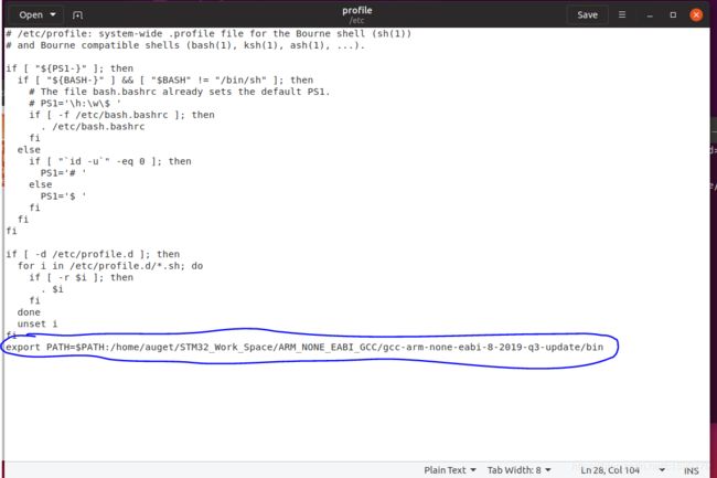
然后保存,关闭。
输入以下命令更新环境变量文件,也可以重启虚拟机更保险:
$ source /etc/profile
或者:
$ . /etc/profile
然后我们在终端输入arm-none,再按tab键,看会不会自动补全为arm-none-eabi-,如果能,证明环境变量添加成功。
执行:
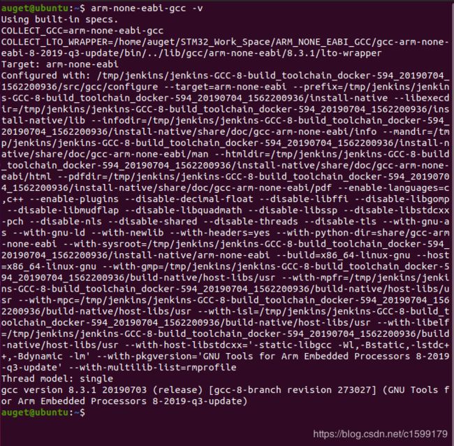
$ arm-none-eabi-gcc -v
查看版本,如果出现以下版本内容,表明成功安装并可以用了(一般需要重启下,否则只能在那一个终端有正确显示,再开个终端就会识别不了命令)。
2、安装jlink驱动
JLink驱动可以在下面这个网站下载deb版本,可以直接双击安装,省去不少麻烦(下载速度较慢,你懂的):
https://www.segger.com/downloads/jlink
在这里建议不要下载太新的版本,因为我们使用的JLink基本上都不太正版,容易被识别出来,导致使用的时候会出现不愉快,不过好像也能使用。这里博主使用的是5.10.19版本。

具体jlink的应用等到程序烧录时会介绍。
3、更改工程核心文件
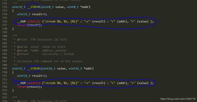
好像keil使用的编译工具是ARMCC,这里用的arm-none-eabi-gcc还是有所不同,要在工程的核心文件中改两行,打开核心文件core_cm3.c,大概是要改下图显示的736和753行:
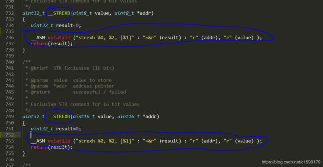
改成下图所示内容:
4、选择工程启动文件
工程启动文件使用的是v3.50库里面提供的启动文件,库路径如下:STM32F10x_StdPeriph_Lib_V3.5.0\STM32F10x_StdPeriph_Lib_V3.5.0\Libraries\CMSIS\CM3\DeviceSupport\ST\STM32F10x\startup\gcc_ride7\startup_stm32f10x_md.s
玩过stm32对这个汇编写的启动文件应该不陌生,具体作用可以网上查一查了解了解,这里我们只是会用即可。
5、编写链接文件
链接文件主要指示连接过程,里面会指示芯片相关信息,比如flash和ram的大小,会跟具体的芯片类型有关系,这里我们使用的是stm32f103c8t6,需要的链接文件也可以在v3.50库里面找到,路径如下:
STM32F10x_StdPeriph_Lib_V3.5.0\STM32F10x_StdPeriph_Lib_V3.5.0\Project\STM32F10x_StdPeriph_Template\TrueSTUDIO\STM3210B-EVAL\stm32_flash.ld
里面具体内容如下:
/*
*****************************************************************************
**
**  File        : stm32_flash.ld
**
**  Abstract    : Linker script for STM32F103VB Device with
**                128KByte FLASH, 20KByte RAM
**
**                Set heap size, stack size and stack location according
**                to application requirements.
**
**                Set memory bank area and size if external memory is used.
**
**  Target      : STMicroelectronics STM32
**
**  Environment : Atollic TrueSTUDIO(R)
**
**  Distribution: The file is distributed 揳s is,?without any warranty
**                of any kind.
**
**  (c)Copyright Atollic AB.
**  You may use this file as-is or modify it according to the needs of your
**  project. Distribution of this file (unmodified or modified) is not
**  permitted. Atollic AB permit registered Atollic TrueSTUDIO(R) users the
**  rights to distribute the assembled, compiled & linked contents of this
**  file as part of an application binary file, provided that it is built
**  using the Atollic TrueSTUDIO(R) toolchain.
**
*****************************************************************************
*/

/* Entry Point */
ENTRY(Reset_Handler)

/* Highest address of the user mode stack */
_estack = 0x20005000;    /* end of 20K RAM */

/* Generate a link error if heap and stack don't fit into RAM */
_Min_Heap_Size = 0;      /* required amount of heap  */
_Min_Stack_Size = 0x100; /* required amount of stack */

/* Specify the memory areas */
MEMORY
{
  FLASH (rx)      : ORIGIN = 0x08000000, LENGTH = 128K
  RAM (xrw)       : ORIGIN = 0x20000000, LENGTH = 20K
  MEMORY_B1 (rx)  : ORIGIN = 0x60000000, LENGTH = 0K
}

/* Define output sections */
SECTIONS
{
  /* The startup code goes first into FLASH */
  .isr_vector :
  {
    . = ALIGN(4);
    KEEP(*(.isr_vector)) /* Startup code */
    . = ALIGN(4);
  } >FLASH

  /* The program code and other data goes into FLASH */
  .text :
  {
    . = ALIGN(4);
    *(.text)           /* .text sections (code) */
    *(.text*)          /* .text* sections (code) */
    *(.rodata)         /* .rodata sections (constants, strings, etc.) */
    *(.rodata*)        /* .rodata* sections (constants, strings, etc.) */
    *(.glue_7)         /* glue arm to thumb code */
    *(.glue_7t)        /* glue thumb to arm code */

    KEEP (*(.init))
    KEEP (*(.fini))

    . = ALIGN(4);
    _etext = .;        /* define a global symbols at end of code */
  } >FLASH


   .ARM.extab   : { *(.ARM.extab* .gnu.linkonce.armextab.*) } >FLASH
    .ARM : {
    __exidx_start = .;
      *(.ARM.exidx*)
      __exidx_end = .;
    } >FLASH

  .ARM.attributes : { *(.ARM.attributes) } > FLASH

  .preinit_array     :
  {
    PROVIDE_HIDDEN (__preinit_array_start = .);
    KEEP (*(.preinit_array*))
    PROVIDE_HIDDEN (__preinit_array_end = .);
  } >FLASH
  .init_array :
  {
    PROVIDE_HIDDEN (__init_array_start = .);
    KEEP (*(SORT(.init_array.*)))
    KEEP (*(.init_array*))
    PROVIDE_HIDDEN (__init_array_end = .);
  } >FLASH
  .fini_array :
  {
    PROVIDE_HIDDEN (__fini_array_start = .);
    KEEP (*(.fini_array*))
    KEEP (*(SORT(.fini_array.*)))
    PROVIDE_HIDDEN (__fini_array_end = .);
  } >FLASH

  /* used by the startup to initialize data */
  _sidata = .;

  /* Initialized data sections goes into RAM, load LMA copy after code */
  .data : AT ( _sidata )
  {
    . = ALIGN(4);
    _sdata = .;        /* create a global symbol at data start */
    *(.data)           /* .data sections */
    *(.data*)          /* .data* sections */

    . = ALIGN(4);
    _edata = .;        /* define a global symbol at data end */
  } >RAM

  /* Uninitialized data section */
  . = ALIGN(4);
  .bss :
  {
    /* This is used by the startup in order to initialize the .bss secion */
    _sbss = .;         /* define a global symbol at bss start */
    __bss_start__ = _sbss;
    *(.bss)
    *(.bss*)
    *(COMMON)

    . = ALIGN(4);
    _ebss = .;         /* define a global symbol at bss end */
    __bss_end__ = _ebss;
  } >RAM

  PROVIDE ( end = _ebss );
  PROVIDE ( _end = _ebss );

  /* User_heap_stack section, used to check that there is enough RAM left */
  ._user_heap_stack :
  {
    . = ALIGN(4);
    . = . + _Min_Heap_Size;
    . = . + _Min_Stack_Size;
    . = ALIGN(4);
  } >RAM

  /* MEMORY_bank1 section, code must be located here explicitly            */
  /* Example: extern int foo(void) __attribute__ ((section (".mb1text"))); */
  .memory_b1_text :
  {
    *(.mb1text)        /* .mb1text sections (code) */
    *(.mb1text*)       /* .mb1text* sections (code)  */
    *(.mb1rodata)      /* read-only data (constants) */
    *(.mb1rodata*)
  } >MEMORY_B1

  /* Remove information from the standard libraries */
  /DISCARD/ :
  {
    libc.a ( * )
    libm.a ( * )
    libgcc.a ( * )
  }
}
对这个文件感兴趣的话也可以网上查一查,这里我们也只是会用即可。
6、编写工程makefile
工程的makefile文件如下:
#工程的名称及最后生成文件的名字
TARGET = project

#设定临时性环境变量
export CC             = arm-none-eabi-gcc
export AS             = arm-none-eabi-as
export LD             = arm-none-eabi-ld
export OBJCOPY        = arm-none-eabi-objcopy

#读取当前工作目录
TOP=$(shell pwd)

#设定包含文件目录
INC_FLAGS= -I $(TOP)/CORE                  \
           -I $(TOP)/CODE/COMMON/INC    \
           -I $(TOP)/CODE/PROCESS/INC             \
           -I $(TOP)/CODE/REMOTE_CONTROLER/REMOTE_CONTROLER/INC       \
           -I $(TOP)/CODE/REMOTE_CONTROLER/REMOTE_CONTROLER_ADC1/INC   \
           -I $(TOP)/CODE/REMOTE_CONTROLER/REMOTE_CONTROLER_DEFINE/INC \
           -I $(TOP)/CODE/REMOTE_CONTROLER/REMOTE_CONTROLER_KEY/INC   \
           -I $(TOP)/CODE/REMOTE_CONTROLER/REMOTE_CONTROLER_NRF24L01/INC \
           -I $(TOP)/CODE/REMOTE_CONTROLER/REMOTE_CONTROLER_SET/INC \
           -I $(TOP)/CODE/REMOTE_CONTROLER/REMOTE_CONTROLER_STRUCT/INC \
           -I $(TOP)/CODE/REMOTE_CONTROLER/REMOTE_CONTROLER_USART1/INC \
           -I $(TOP)/FWLIB/INC             \
           -I $(TOP)/IT/INC             \
           -I $(TOP)/SYSTEM/INC

#
CFLAGS =  -W -Wall -g -mcpu=cortex-m3 -mthumb -D STM32F10X_MD -D USE_STDPERIPH_DRIVER $(INC_FLAGS) -O0 -std=gnu11
C_SRC=$(shell find ./ -name '*.c')
C_OBJ=$(C_SRC:%.c=%.o)
#

#
ASFLAGS= -W -Wall -g -Wall -mcpu=cortex-m3 -mthumb
ASM_SRC=$(shell find ./ -name '*.s')
ASM_OBJ=$(ASM_SRC:%.s=%.o)
#

#
.PHONY: all clean update
#

#
all:$(C_OBJ) $(ASM_OBJ)
	$(CC) $(C_OBJ) $(ASM_OBJ) -T Linker.ld -o $(TARGET).elf   -mthumb -mcpu=cortex-m3 -Wl,--start-group -lc -lm -Wl,--end-group -specs=nano.specs -specs=nosys.specs -static -Wl,-cref,-u,Reset_Handler -Wl,-Map=Project.map -Wl,--gc-sections -Wl,--defsym=malloc_getpagesize_P=0x80
	$(OBJCOPY) $(TARGET).elf  $(TARGET).bin -Obinary
	$(OBJCOPY) $(TARGET).elf  $(TARGET).hex -Oihex
#

#
$(C_OBJ):%.o:%.c
	$(CC) -c $(CFLAGS) -o $@ $<
#

#
$(ASM_OBJ):%.o:%.s
	$(AS) -c $(ASFLAGS) -o $@ $<
#

#
clean:
	rm -f $(shell find ./ -name '*.o')
	rm -f $(shell find ./ -name '*.d')
	rm -f $(shell find ./ -name '*.map')
	rm -f $(shell find ./ -name '*.elf')
	rm -f $(shell find ./ -name '*.bin')
	rm -f $(shell find ./ -name '*.hex')
	rm -f $(shell find ./ -name '*.cdep')
这里makefile的主要功能就是把工程里的所有.c和.s文件编译生成.o文件,然后根据链接文件把生成的.o文件链接生成目的文件,也就是最后用来下载的.hex和.bin文件。
7、使用make进行编译链接并生成.bin和.hex文件
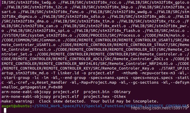
从现在开始就是激动人心的时刻了,在终端进入makefile所在目录,执行make命令,如果你看到终端很流畅的输出一坨又一坨的内容,并最终执行完毕,没有错误,然后你再makefile同级目录多出来了一个.hex文件和一个.bin文件,那么恭喜你,离成功不远了,准确的说应该是离成功就差下载一步了。博主走到这一步时,别提有多开心了。
8、使用jlink对芯片进行烧录
走到这一步就是见证奇迹的时刻了,在终端输入以下命令进入JLink工作目录:
$ cd /opt/SEGGER/JLink/
如果你没有这个目录,那么很不幸,JLink没有安装成功,请移步第二步。
如果有,接下来确定硬件连接正确,然后把USB连到虚拟机上,在终端执行命令:
$ ./JLinkExe
出现以下画面证明连接成功并进入工作区:

然后按照提示输入:
connect
出现下面结果,提示输入设备型号:

由于我们用的c8t6系列,所以输入:
STM32F103C8
执行后会让选择连接模式:SWD/JTAG

这里博主用的时SWD,所以输入SWD:

然后让选通信速率,这里博主选的4000,问题不大,建议不要选太大。
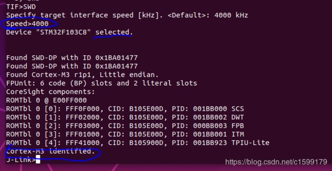
出现以上的结果证明配置成功了,接下来就是下载了:
输入:
loadbin <.bin文件所在目录> <下载起始地址>
得到下面的结果证明下载成功了,奇迹见证完毕:
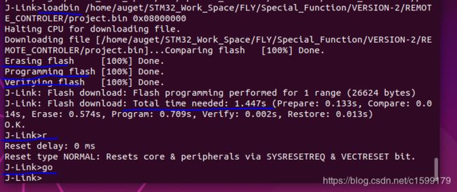
这里下载后板子不会自动执行,分别输入r命令和go命令对板子进行复位和启动,板子就执行了。
最后,附上JLink常用命令(可以输入问号获取):
J-Link>?
Available commands are:
----------------------
f          Firmware info
h          halt
g          go
Sleep      Waits the given time (in milliseconds). Syntax: Sleep
s          Single step the target chip
st         Show hardware status
hwinfo     Show hardware info
mem        Read memory. Syntax: mem  [:],  (hex)
mem8       Read  8-bit items. Syntax: mem8  [:],  (hex)
mem16      Read 16-bit items. Syntax: mem16 [:],  (hex)
mem32      Read 32-bit items. Syntax: mem32 [:],  (hex)
w1         Write  8-bit items. Syntax: w1 [:],  (hex)
w2         Write 16-bit items. Syntax: w2 [:],  (hex)
w4         Write 32-bit items. Syntax: w4 [:],  (hex)
erase      Erase internal flash of selected device. Syntax: Erase
wm         Write test words. Syntax: wm
is         Identify length of scan chain select register
ms         Measure length of scan chain. Syntax: ms
mr         Measure RTCK react time. Syntax: mr
q          Quit
qc         Close JLink connection and quit
r          Reset target         (RESET)
rx         Reset target         (RESET). Syntax: rx
RSetType   Set the current reset type. Syntax: RSetType
Regs       Display contents of registers
wreg       Write register.   Syntax: wreg ,
moe        Shows mode-of-entry, meaning: Reason why CPU is halted
SetBP      Set breakpoint.   Syntax: SetBP  [A/T] [S/H]
SetWP      Set Watchpoint. Syntax:  [R/W] [ [] [A-Mask]]
ClrBP      Clear breakpoint. Syntax: ClrBP
ClrWP      Clear watchpoint. Syntax: ClrWP
VCatch     Write vector catch. Syntax: VCatch
loadfile   Load data file into target memory.
             Syntax: loadfile , []
             Supported extensions: *.bin, *.mot, *.hex, *.srec
              is needed for bin files only.
loadbin    Load *.bin file into target memory.
             Syntax: loadbin ,
savebin    Saves target memory into binary file.
             Syntax: savebin , ,
verifybin  Verfies if the specified binary is already in the target memory at the specified address.
             Syntax: verifybin ,
SetPC      Set the PC to specified value. Syntax: SetPC
le         Change to little endian mode
be         Change to big endian mode
log        Enables log to file.  Syntax: log
unlock     Unlocks a device. Syntax: unlock
           Type unlock without  to get a list
           of supported device names.
           nRESET has to be connected
term       Test command to visualize _ReportOutf output from the target device,
           using DCC (SEGGER DCC handler running on target)
ReadAP     Reads a CoreSight AP register.
           Note: First read returns the data of the previous read.
           An additional read of DP reg 3 is necessary to get the data.
ReadDP     Reads a CoreSight DP register.
           Note: For SWD data is returned immediately.
           For JTAG the data of the previous read is returned.
           An additional read of DP reg 3 is necessary to get the data.
WriteAP    Writes a CoreSight AP register.
WriteDP    Writes a CoreSight DP register.
SWDSelect  Selects SWD as interface and outputs
           the JTAG -> SWD switching sequence.
SWDReadAP  Reads a CoreSight AP register via SWD.
           Note: First read returns the data of the previous read.
           An additional read of DP reg 3 is necessary to get the data.
SWDReadDP  Reads a CoreSight DP register via SWD.
           Note: Correct data is returned immediately.
SWDWriteAP Writes a CoreSight AP register via SWD.
SWDWriteDP Writes a CoreSight DP register via SWD.
Device     Selects a specific device J-Link shall connect to
           and performs a reconnect.
           In most cases explicit selection of the device is not necessary.
           Selecting a device enables the user to make use of the J-Link
           flash programming functionality as well as using unlimited
           breakpoints in flash memory.
           For some devices explicit device selection is mandatory in order
           to allow the DLL to perform special handling needed by the device.
ExpDevList Exports the device names from the DLL internal
           device list to a text file
             Syntax: ExpDevList
PowerTrace Perform power trace (not supported by all models)
Syntax: PowerTrace  [ ]
: File to store power trace data to
: 32-bit mask to specify what channels shall be enabled
: Sampling frequency in Hz (0 == max)
:       0: No reference count
                     1: Number of bytes transmitted on SWO
---- CP15 ------------
rce        Read CP15.  Syntax: rce , , ,
wce        Write CP15. Syntax: wce , , , ,
---- ICE -------------
Ice        Show state of the embedded ice macrocell (ICE breaker)
ri         Read Ice reg.  Syntax: ri (hex)
wi         Write Ice reg. Syntax: wi , (hex)
---- TRACE -----------
TClear     TRACE - Clear buffer
TSetSize   TRACE - Set Size of trace buffer
TSetFormat TRACE - SetFormat
TSR        TRACE - Show Regions (and analyze trace buffer)
TStart     TRACE - Start
TStop      TRACE - Stop
---- SWO -------------
SWOSpeed   SWO - Show supported speeds
SWOStart   SWO - Start
SWOStop    SWO - Stop
SWOStat    SWO - Display SWO status
SWORead    SWO - Read and display SWO data
SWOShow    SWO - Read and analyze SWO data
SWOFlush   SWO - Flush data
SWOView    SWO - View terminal data
---- PERIODIC --------
PERConf    PERIODIC - Configure
PERStart   PERIODIC - Start
PERStop    PERIODIC - Stop
PERStat    PERIODIC - Display status
PERRead    PERIODIC - Read and display data
PERShow    PERIODIC - Read and analyze data
---- File I/O --------
fwrite     Write file to emulator
fread      Read file from emulator
fshow      Read and display file from emulator
fdelete    Delete file on emulator
fsize      Display size of file on emulator
flist      List directory on emulator
SecureArea Creates/Removes secure area on probe
---- Test ------------
TestHaltGo   Run go/halt 1000 times
TestStep     Run step 1000 times
TestCSpeed   Measure CPU speed.
             Parameters: []
TestWSpeed   Measure download speed into target memory.
             Parameters:  [ []]
TestRSpeed   Measure upload speed from target memory.
             Parameters: [ [] []]
TestNWSpeed  Measure network download speed.
             Parameters: [ []]
TestNRSpeed  Measure network upload speed.
             Parameters: [ []]
---- JTAG ------------
Config     Set number of IR/DR bits before ARM device.
             Syntax: Config ,
speed      Set target interface speed. Syntax: speed |auto|adaptive, e.g. speed 2000, speed a
i          Read JTAG Id (Host CPU)
wjc        Write JTAG command (IR). Syntax: wjc (hex)
wjd        Write JTAG data (DR). Syntax: wjd (hex), (dec)
RTAP       Reset TAP Controller using state machine (111110)
wjraw      Write Raw JTAG data. Syntax: wjraw , ,
rt         Reset TAP Controller (nTRST)
---- JTAG-Hardware ---
c00        Create clock with TDI = TMS = 0
c          Clock
tck0       Clear TCK
tck1       Set   TCK
0          Clear TDI
1          Set   TDI
t0         Clear TMS
t1         Set   TMS
trst0      Clear TRST
trst1      Set   TRST
r0         Clear RESET
r1         Set   RESET
---- Connection ------
usb        Connect to J-Link via USB.  Syntax: usb , where port is 0..3
ip         Connect to J-Link ARM Pro or J-Link TCP/IP Server via TCP/IP.
           Syntax: ip
---- Configuration ---
si         Select target interface. Syntax: si ,
           where  can be any supported target interface (e.g SWD, JTAG, ICSP, FINE, ...
power      Switch power supply for target. Syntax: power  [perm],
           where State is either On or Off. Example: power on perm
wconf      Write configuration byte. Syntax: wconf ,
rconf      Read configuration bytes. Syntax: rconf
license    Shows a list of all available license commands
ipaddr     Show/Assign IP address and subnetmask of/to the connected J-Link.
gwaddr     Show/Assign network gateway address of/to the connected J-Link.
dnsaddr    Show/Assign network DNS server address of/to the connected J-Link.
conf       Show configuration of the connected J-Link.
ecp        Enable the  J-Link control panel.
calibrate  Calibrate the target current measurement.
selemu     Select a emulator to communicate with,
           from a list of all emulators which are connected to the host
           The interfaces to search on, can be specified
             Syntax: selemu [  ...]
ShowEmuList Shows a list of all emulators which are connected to the host.
            The interfaces to search on, can be specified.
             Syntax: ShowEmuList [  ...]
----------------------