【Metal2剖析(一):MTLRenderPassDescriptor和MTLVertexDescriptor】
MTLRenderPassDescriptor和MTLVertexDescriptor是Metal引擎框架中比较重要的两个类,分别用来配置渲染末期渲染结果的去向和渲染初期顶点数据的映射传送。

文章目录
- 一、MTLRenderPassDescriptor渲染通道描述
- 1.1 MTLRenderPassDescriptor是什么
- 1.2 MTLRenderPassAttachmentDescriptor介绍
- 1.3 MTLRenderPassDescriptor的用法
- 二、MTLVertexDescriptor顶点结构描述
- 2.1 MTLVertexDescriptor是什么
- 2.2 着色函数和顶点数据
- 2.2.1 顶点数据结构以及数据获取
- 2.2.2 将数据buffer从CPU传送给GPU中的着色函数
- Argument Tables传送数据
- 三、总结
- 参考文章
一、MTLRenderPassDescriptor渲染通道描述
1.1 MTLRenderPassDescriptor是什么
关于MTLRenderPassDescriptor苹果官方的解释比较简单,初学者可能难以准确理解它的作用和用法。
官方的定义为:一组接收渲染Pass的结果的渲染目标(RT)。
官方的定义其实很准确简洁,就是用来设置我们的渲染RT的,同时是一组,是一个数组,那么就是多个RT,自然可以想到MRT。所以可以理解为用来设置GBuffer的对象。
官方文档另外还解释如下:一个MTLRenderPassDescriptor对象包含一组attachments,作为rendering pass产生的像素的目的地。MTLRenderPassDescriptor还可以用来设置目标缓冲来保存rendering pass产生的可见性信息(光照可见性等用法,也就是自定义GBuffer的用法)。
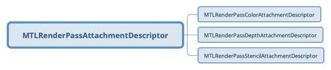
另外除了用于保存颜色信息的color attachments,MTLRenderPassDescriptor还分别包含一个depthAttachment和stencilAttachment,用于保存深度缓冲数据和模板缓冲数据。
他们的定义如下:
@property (readonly) MTLRenderPassColorAttachmentDescriptorArray *colorAttachments;

@property (copy, nonatomic, null_resettable) MTLRenderPassDepthAttachmentDescriptor *depthAttachment;

@property (copy, nonatomic, null_resettable) MTLRenderPassStencilAttachmentDescriptor *stencilAttachment;
最后看一下MTLRenderPassDescriptor在Metal管线结构中的位置:

可以看到它是直接服务于MTLRenderCommandEncoder进行配置的,其下有对应的AttachmentDescriptor用于配置不同的通道(颜色通道和深度、模板缓冲通道),不同的通道对应一张Texture用于缓存数据,当然MTLTexture在创建初始化时也有其对应的TextureDescriptor进行配置。
1.2 MTLRenderPassAttachmentDescriptor介绍
MTLRenderPassDescriptor的colorAttachments、depthAttachment、stencilAttachment对应的类都是继承自MTLRenderPassAttachmentDescriptor的,用法类似,可以具体配置他们的属性。
MTLRenderPassDescriptor最常用的属性是下面几个:
-
@property (nullable, nonatomic, strong) id这个就是RT,要把初始化好的MTLTexture设置到对应的attachment;texture; -
@property (nonatomic) MTLLoadAction loadAction;这个是在渲染开始时的RT动作,是清空RT还是保留原信息还是无所谓,默认是无所谓MTLLoadActionDontCare; -
@property (nonatomic) MTLStoreAction storeAction;渲染结束时的动作,默认也是MTLLoadActionDontCare; -
@property (nonatomic) MTLClearColor clearColor;这个是loadAction为MTLLoadActionClear的清空颜色。
还有几个比较重要的属性适用于设置Tile based rendering的:
@property (nonatomic) NSUInteger threadgroupMemoryLength;
@property (nonatomic) NSUInteger tileWidth;
@property (nonatomic) NSUInteger tileHeight;
threadgroupMemoryLength 设置的是持久性线程组内存分配下每个tile的字节大小,tileWidth 和 tileHeight 设置的是每个tile的像素宽高,默认是0(0表示Metal自动选择合适的宽高来适配本地内存)。
另外还有mipmap level等属性的设置,imageblock采样点的大小设置,可根据需要查看MTLRenderPassAttachmentDescriptor的代码声明。
1.3 MTLRenderPassDescriptor的用法
MTLRenderPassDescriptor是用来配置渲染结果的输出去向,缓存到一个或多个RT(MTLTexture)上,用于Tile阶段的后续计算或者输出到屏幕上。通常MTLRenderPassDescriptor对象设置好后会用来创建当前commandBuffer下的renderEncoder:
id _myRenderEncoder = [commandBuffer renderCommandEncoderWithDescriptor:_renderPassDescriptor];
然后就可以使用这个renderEncoder进行后面的pipeLine设置,绘制图形。
MTLRenderPassDescriptor的一个创建和配置示例如下:
    MTLRenderPassDescriptor _renderPassDescriptor =  [[MTLRenderPassDescriptor alloc] init];

    _renderPassDescriptor.colorAttachments[0].texture = _targetRT1;
    GetMTLTexture(targetRTs[i]);
    _renderPassDescriptor.colorAttachments[0].loadAction = MTLLoadActionClear;
    _renderPassDescriptor.colorAttachments[0].storeAction = MTLStoreActionStore;

    _renderPassDescriptor.colorAttachments[1].texture = _targetRT2;
    _renderPassDescriptor.colorAttachments[1].loadAction = MTLLoadActionClear;
    _renderPassDescriptor.colorAttachments[1].storeAction = MTLStoreActionDontCare;

    _renderPassDescriptor.depthAttachment.texture = _depthData;
    _renderPassDescriptor.depthAttachment.loadAction = MTLLoadActionClear;
    _renderPassDescriptor.depthAttachment.storeAction = MTLStoreActionDontCare;
示例设置了两个colorAttachment和对应的depthAttachment。既然是两个colorAttachment那么在shader中fragment着色函数的返回自然要一一对应设置两个输出通道:
// FS输出结构体定义
struct FSOutput
{
    half4 frag_data0 [[color(0)]];
    half4 frag_data1 [[color(1)]];
};

fragment FSOutput fragmentQuadMain(VSOutput input [[stage_in]],
                                   texture2d colorTexture [[ texture(0) ]])
{
    FSOutput out;
    constexpr sampler textureSampler (mag_filter::linear,
                                      min_filter::linear);
    // Sample the texture to obtain a color
    const half4 colorSample = colorTexture.sample(textureSampler, input.texcoord);
    // return the color of the texture to colorAttachments[0]
    out.frag_data0 = colorSample;
    // return test color to colorAttachments[1]
    out.frag_data1 = half4(1.0f,0,0,0);
    return out;
}
注意颜色通道是通过[[color(id)]]属性来对应的,[[color(1)]]对应MTLRenderPassDescriptor中的colorAttachments[i]。
二、MTLVertexDescriptor顶点结构描述
2.1 MTLVertexDescriptor是什么
官方对MTLVertexDescriptor的解释:
MTLVertexDescriptor是用来描述如何组织顶点数据以及如何映射到shader中顶点着色函数的对象。
一个MTLVertexDescriptor对象用来配置顶点数据如何在内存中存储,以及映射到vertex shader中的attribute属性上。
一个pipeline state表示图形渲染管线的状态,包括shaders,混合,多采样和可见性测试。对于每一个pipeline state,只会对应一个MTLVertexDescriptor对象。在创建pipeline state在时如果配置了MTLRenderPipelineDescriptor对象到pipeline state的vertexDescriptor属性上,那么这个MTLRenderPipelineDescriptor对象构建的顶点layout组织结构就会应用于和这个pipeline相关的函数。
总之,每个渲染管线只会设置一个MTLVertexDescriptor,来组织顶点结构,而MTLVertexDescriptor的设置时取决于我们的模型数据的,例如我们加载一个obj模型,它的顶点数据可能有position,normal,uv,tangent等,我们需要设置与之对应的MTLVertexDescriptor结构来正确解析和接受模型数据,并将数据映射传到vertex shader中进行计算。可以说MTLVertexDescriptor是模型数据在CPU代码中的表示到GPU shader函数中属性数据的映射粘合剂。
PLUS:但MTLVertexDescriptor并不是必须使用的,因为将顶点缓冲VB传送给vertex shader的方式除了用MTLVertexDescriptor描述顶点结构然后在顶点着色函数中用[[stage_in]]属性接收,还可以直接通过设置顶点buffer传给顶点着色函数[[buffer(id)]],并根据[[ vertex_id]]属性定位当前顶点的数据。具体用法后面介绍。
2.2 着色函数和顶点数据
我们知道函数本质上是用来转换数据的,将输入的数据转换成输出的数据,shader中的着色函数也一样。例如:vertex function将模型空间的顶点数据转换成裁剪空间的顶点数据,fragment function将光栅化的数据转换成片段最终的颜色数据。
但我们要处理的数据,例如模型数据,一般都是外部数据,因此我们的函数要有参数,将外部数据通过参数传递给函数内部进行处理。而着色函数是由GPU调用的,我们在CPU上写的逻辑代码不能直接将数据传送给着色函数。下面就解析我们是如何通过MTLVertexDescriptor配置等方式将模型数据传送给着色函数的。
2.2.1 顶点数据结构以及数据获取
这里举例子设计一个非常简单的顶点数据结构如下:
typedef struct
{
    vector_float2 position;
    vector_float2 uv;
} AAPLVertex;
就假设我们的模型顶点数据只有顶点位置和纹理坐标这两个属性,当然实际上一般模型还会有法线、切线等属性。
然后我们利用这个数据结构简单自定义一个对应的模型数据如下:
static const AAPLVertex verts[] =
    {
        // Pixel positions, Texture coordinates
        { {  1.0,  -1.0 },  { 1.f, 1.f } },
        { { -1.0,  -1.0 },  { 0.f, 1.f } },
        { { -1.0,   1.0 },  { 0.f, 0.f } },

        { {  1.0,  -1.0 },  { 1.f, 1.f } },
        { { -1.0,   1.0 },  { 0.f, 0.f } },
        { {  1.0,   1.0 },  { 1.f, 0.f } },
    };
这个模型定一个其实是一个二维quad矩形模型,由两个三角形组成,一共6个顶点。
然后我们需要将模型数据拷贝到我们程序的buffer中,这里是在Objective-C环境下,我们将数据放到准备好的MTLBuffer中,拷贝方式有下面两种:
id _quadBuffer;

// 第一种直接在创建buffer时使用顶点数据初始化:
_quadBuffer = [_device newBufferWithBytes:verts length:sizeof(verts) options:MTLResourceStorageModeShared];

// 第二种先创建buffer,之后在合适的时机把数据拷贝进去
_quadBuffer = [_device newBufferWithLength:1024 options: MTLResourceStorageModeShared];
//...
memcpy(_quadBuffer.contents, verts, sizeof(AAPLVertex) * 6);
2.2.2 将数据buffer从CPU传送给GPU中的着色函数
Metal将数据传给GPU的方式比较灵活,可以使用传统的Argument Table直接setBuffer给着色函数,也可以通过这里讲的使用MTLVertexDescriptor配置走stage流程传送顶点数据,另外还可以使用最新的特性Argument Buffer封装数据进行统一传送。
这里先介绍通过定义和配置MTLVertexDescriptor对象,来自动传送数据到管线各阶段的方式。
CPU传送数据给GPU
根据上面的顶点的数据结构,我们应该定义MTLVertexDescriptor对象并按如下进行配置。
    MTLVertexDescriptor _unityVertexDescriptor = [[MTLVertexDescriptor alloc] init];

    // Positions.
    _unityVertexDescriptor.attributes[0].format = MTLVertexFormatFloat2;
    _unityVertexDescriptor.attributes[0].offset = 0;
    _unityVertexDescriptor.attributes[0].bufferIndex = 0;

    // Texture coordinates.
    _unityVertexDescriptor.attributes[1].format = MTLVertexFormatFloat2;
    _unityVertexDescriptor.attributes[1].offset = 8;
    _unityVertexDescriptor.attributes[1].bufferIndex = 0;

    // Position Buffer Layout
    _unityVertexDescriptor.layouts[0].stride = 16;
    _unityVertexDescriptor.layouts[0].stepRate = 1;
    _unityVertexDescriptor.layouts[0].stepFunction = MTLVertexStepFunctionPerVertex;
可见由于我们的顶点数据只有position和uv两个属性,因此MTLVertexDescriptor只配置了两个属性,position和uv都只有2个浮点数,因此他们的属性格式format为MTLVertexFormatFloat2。这里同一个顶点的不同属性是连续定义在同一个buffer上的所以需要设置offset,position的2个浮点数占用4*2=8个字节,所以uv的offset为8。然后需要注意MTLVertexDescriptor的layouts配置,由于是连续定义在同一个buffer中所以这里只配置了一个layouts[0],stride属性表示每次去取一个顶点数据的数据跨度,这里每个顶点数据占16字节,所以stride设置为16。
另外关于stepRate和stepFunction的含义和作用,之后在另一篇文章中的单独总结,主要用在Instance rendering和Tessellating等技术中。
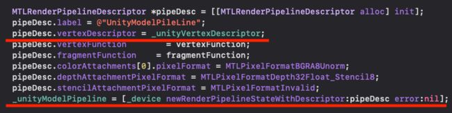
现在看下MTLVertexDescriptor在管线结构中的位置:

可以看到MTLVertexDescriptor是服务于RenderPipelineDescriptor用来配置Vertex Format顶点结构的,而RenderPipelineDescriptor用来创建我们的pipeline状态对象。于是它们的用途和关系如下:
顶点结构配置好了之后,在绘制模型之间要记得将顶点数据buffer传送给默认的buffer(0):
[_myRenderEncoder setVertexBuffer: _quadBuffer offset:0 atIndex:0];
这样在指令提交后数据就会按照指定格式往GPU传送了。
上面说到代码中MTLVertexDescriptor是将数据连续存储在同一个buffer上,实际上也可以将数据分别并行放到多个buffer上,例如上面position数据放到第一个buffer,uv放到第二个buffer上。下面介绍这种方式下该如何配置MTLVertexDescriptor以及两种方式的区别和目的是什么。
介绍两种方式的区别之前先引入OpenGL中的两个概念:SOA和AOS。
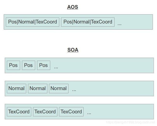
看到图示应该很容易理解,AOS(Array Of Structure)就是我们上面例子中MTLVertexDescriptor的组织方式了,同一个顶点的所有属性在同一个buffer依次排列存储,然后继续排列存储下一个顶点数据,如此类推,这样的好处是符合面向对象的布局思路。而SOA(Structure Of Array)是AOS的一个变换,不同于之前一些属性结构的集合组成的结构数组,现在我们有一个结构来包含多个数组,每个数组只包含一个属性,这样GPU可以使用同一个index索引去读取每个数组中的属性,GPU读取比较整齐,这种方法对于某一些3D文件格式尤其合适。
再放一个国外友人的解释:
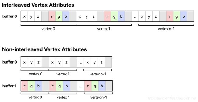
他解释这两种组织结构为重叠顶点属性和非重叠顶点属性。原理类似。
理解了两种组织结构的原理,那么现在看在非重叠顶点属性的SOA组织结构下应该如何定义和配置我们的MTLVertexDescriptor对象:
    MTLVertexDescriptor _unityVertexDescriptor = [[MTLVertexDescriptor alloc] init];

    // Positions.
    _unityVertexDescriptor.attributes[0].format = MTLVertexFormatFloat2;
    _unityVertexDescriptor.attributes[0].offset = 0;
    _unityVertexDescriptor.attributes[0].bufferIndex = 0;

    // Texture coordinates.
    _unityVertexDescriptor.attributes[1].format = MTLVertexFormatFloat2;
    _unityVertexDescriptor.attributes[1].offset = 0;
    _unityVertexDescriptor.attributes[1].bufferIndex = 0;

    // Position Buffer Layout
    _unityVertexDescriptor.layouts[0].stride = 8;
    _unityVertexDescriptor.layouts[0].stepRate = 1;
    _unityVertexDescriptor.layouts[0].stepFunction = MTLVertexStepFunctionPerVertex;

    _unityVertexDescriptor.layouts[1].stride = 8;
    _unityVertexDescriptor.layouts[1].stepRate = 1;
    _unityVertexDescriptor.layouts[1].stepFunction = MTLVertexStepFunctionPerVertex;
可见由于我们的顶点有两个属性,因此我们可以将顶点数据放到两个buffer上,一个保存position数据,一个保存uv数据。因此这里MTLVertexDescriptor对象的layouts需要定义两个,分别对应两个buffer,每个属性有2个float数据,因此GPU取数据的stride步长都为8。另外现在每个属性占用一个buffer,所以attributes的offset都为0了。
在着色函数中接收并使用顶点数据
上面介绍中GPU已经取到了数据,现在我们要在着色函数中进行接收。无论是采用的上面的哪种数据组织方式,对于在着色函数中的数据接收都是一样的,组织结构不同只是GPU取数据和存储数据方式不同而已。
根据顶点数据结构,在shader中定义的顶点属性结构应该如下:
struct Vertex
{
    float2 position [[attribute(0)]];
    float2 texCoord [[attribute(1)]];
};
可见数据是通过[[attribute(id)]]属性映射的,属性的命名无所谓,这样position属性和uv属性就映射到了shader中的这两个属性变量中。并在vertex function中以属性参数[[stage_in]]自动传送给着色函数内部:
vertex VSOutput vertexMain(Vertex input [[stage_in]])
{
    // ...
}
注意[[stage_in]]是自动接收来自buffer(0)的顶点数据的,因此这种方式下CPU中要将顶点数据传给buffer(0)。
Argument Tables传送数据
除了顶点数据,我们还需要往shader中传送一些其他数据资源,例如:材质、其他数据缓冲、采样器等等。这些数据是可以直接调用renderEncoder的API往里面传送的。
Argument Tables就是各种资源的列表,每个vertex function和fragment function都对应一个这样的资源列表,通过setVertexBuffer,setFragmentBuffer,setFragmentTexture等函数传入。

table中buffer、texture、sampler的数量取决于硬件设备,但是开发中可以认为至少可以传入31个buffer和texture,和16个sampler。
了解了Argument Tables后现在介绍第二种往着色函数传送顶点数据的方式,即通过setBuffer将顶点数据以普通资源的方式传给vertex function,并根据vertex_id手动定位当前的顶点数据。
这总方式下就不需要定义和使用MTLVertexDescriptor对象了。模型数据结构的定义要和模型中的数据对应好,然后同样拷贝到MTLTBuffer中,然后将要绘制时使用renderEncoder传入buffer:
[_myRenderEncoder setVertexBuffer:_quadBuffer offset:0 atIndex:0]; // 这里atIndex参数不一定为0,只要在shader vertex function中对应好即可
shader中在vertex function接收顶点数组:
vertex VSOutput vertexQuadMain(uint vertexID [[ vertex_id]],
                               constant AAPLVertex *vertexArr [[buffer(0)]])
{
    VSOutput out;
    out.pos = float4(vertexArr[vertexID].position,0.0,1.0);
    out.texcoord = vertexArr[vertexID].uv;
    return out;
}
三、总结
这篇文章主要总结了Metal引擎管线结构中MTLRenderPassDescriptor和MTLVertexDescriptor两个重要的对象的用法,并引申辐射了相关的一些知识点,挖掘了一些容易忽视和误解的细节。
文中有的介绍了某些功能的多种实现方案,这里参考Warren Moore的文章列出如下几条实践建议:
- 尽量使用MTLRenderPassDescriptor的方式来传送顶点数据VB,这样组织内存结构更加灵活清晰,减轻运行时映射数据的压力,一定程度上优化效率;
- 倾向于还是使用非重叠属性AOS的顶点组织方式,特别在不是每个顶点属性都会在每个shader中用到的情况下,否则会容易出现buffer闲置无用的情况;
- 另外文中介绍的时候都是说非重叠属性的组织方式就是每个属性对应一个自己的buffer,实际上不一定,也可以在同一个buffer上利用offset来实现,即buffer的第一个offset部分依次排布所有顶点的position数据,然后第二个offset放所有顶点的uv,以此类推。
参考文章
https://metalbyexample.com/vertex-descriptors/
https://developer.apple.com/documentation/metal/mtlvertexdescriptor?language=objc
https://developer.apple.com/documentation/metal/mtlrenderpassdescriptor?language=objc
https://blog.csdn.net/cordova/article/details/102079994