Android图形显示系统——下层显示4:图层合成上(合成原理与3D合成)
Android显示之图层合成
要点
1.图层合成指综合各个窗口的绘制内容,送往LCD显示的过程。从原理上可分为在线合成与离线合成两种方式。
2.在Android的SurfaceFlinger代码流程中,图层合成方式分3D合成(OpenGL)和硬件合成两大类。
3.图形系统采用垂直同步Vsync机制,由LCD上报vsync,触发图层合成。
图层合成的原理
什么是图层合成
以Android原生版本的Launcher为例,这个场景下有四个图层,状态栏、导航栏由SystemUI绘制,壁纸由壁纸服务提供,图标由Launcher应用绘制,图层合成就是把这四个图层按既定的显示区域,展现到显示屏上。
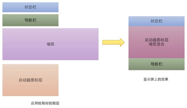
这幅图描述的是带虚拟导航栏的情况,导航栏在最下,状态栏(显示电池容量、时间的那个)在最上,中间大块的区域由墙纸和图标层混合而得,其中墙纸只取一部分。

这幅是小米平板的一个截屏,由于没有虚拟导航栏,它只有三个图层。图标层中空白部分的alpha值为0,其余部分为255,这样在与墙纸混合时,便可形成遮档效果。
三个图层是怎么看出来的呢,
输 adb shell dumpsys SurfaceFlinger :

截取出这段信息,这段信息是SurfaceFlinger告知硬件合成器如何进行合成的。最后一个FramebufferTarget是目标层,不算进去,参与合成的图层是三个,分别是
com.android.systemui.ImageWallpaper,
com.miui.home/com.miui.home.launcher.Launcher,
StatusBar
至于其他各个参数是什么意思到后面再讲。
合成方式
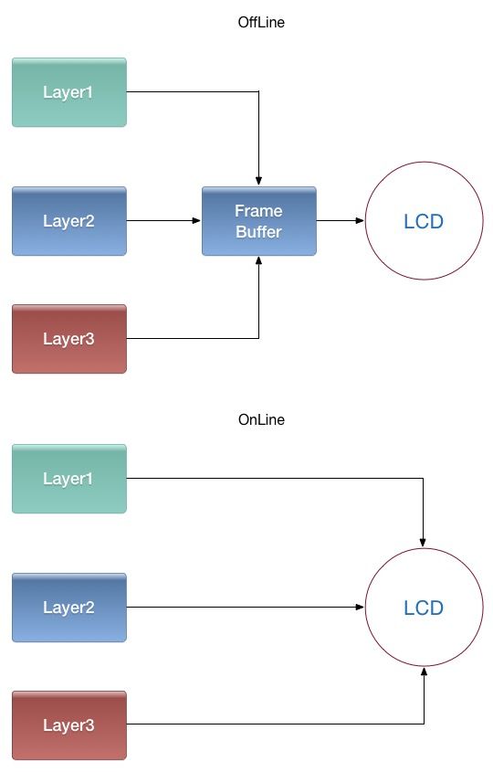
离线合成
先将所有图层画到一个最终层(FrameBuffer)上,再将FrameBuffer送到LCD显示。由于合成FrameBuffer与送LCD显示一般是异步的(线下生成FrameBuffer,需要时线上的LCD去取),因此叫离线合成。
在线合成
不使用FrameBuffer,在LCD需要显示某一行的像素时,用显示控制器将所有图层与该行相关的数据取出,合成一行像素送过去。只有一个图层时,又叫Overlay技术。
由于省去合成FrameBuffer时读图层,写FrameBuffer的步骤,大幅降低了内存传输量,减少了功耗,但这个需要硬件支持。
效率对比
大部分情况下,在线合成比起离线合成有很明显的优势,大幅降低了内存带宽的消耗。不过对于多屏显示,静态场景(仅限LCD不带缓存的情况),离线合成会有优势,做下简单的计算不难推得。
SurfaceFlinger服务
SurfaceFlinger是Android里面用于提供图层合成的服务,负责给应用层提供窗口,并按指定位置合成所有图层到屏幕。
SurfaceFlinger的代码位于
frameworks/native/services/surfaceflinger
目录下。
SurfaceFlinger启动
见 frameworks/native/services/surfaceflinger/main_surfaceflinger.cpp
典型的 binder 服务端写法
#include ps(ProcessState::self());
ps->startThreadPool();
// instantiate surfaceflinger
sp flinger = new SurfaceFlinger();
setpriority(PRIO_PROCESS, 0, PRIORITY_URGENT_DISPLAY);
set_sched_policy(0, SP_FOREGROUND);
// initialize before clients can connect
flinger->init();
// publish surface flinger
sp sm(defaultServiceManager());
sm->addService(String16(SurfaceFlinger::getServiceName()), flinger, false);
// run in this thread
flinger->run();
return 0;
} SurfaceFlinger中的图层合成流程
SurfaceFlinger采用Commander设计模式,SurfaceFlinger主线程接受消息,形成消息队列,逐个处理消息队列中的信息。
因此直接从onMessageReceived看起
void SurfaceFlinger::onMessageReceived(int32_t what) {
    ATRACE_CALL();
    switch (what) {
    case MessageQueue::TRANSACTION:
        handleMessageTransaction();
        break;
    case MessageQueue::INVALIDATE:
        handleMessageTransaction();
        handleMessageInvalidate();
        signalRefresh();
        break;
    case MessageQueue::REFRESH:
        handleMessageRefresh();
        break;
    }
}
handleMessageRefresh处理合成任务:
void SurfaceFlinger::handleMessageRefresh() {
    /*Systrace,打该函数时间*/
    ATRACE_CALL();
    /*调Layer的onPreComposition方法,主要是标志一下Layer已经被用于合成*/
    preComposition();
    /*若Layer的位置/先后顺序/可见性发生变化,重新计算Layer的目标合成区域和先后顺序*/
    rebuildLayerStacks();
    /*配置硬件合成器,调hwc的prepare方法*/
    setUpHWComposer();
    /*当打开开发者选项中的“显示Surface刷新”时,额外为产生变化的图层绘制闪烁动画*/
    doDebugFlashRegions();
    /*执行合成主体,对3D合成而言,调opengl的drawcall,对硬件合成而言,调hwc的set方法*/
    doComposition();
    /*主要用于调试,调Layer的onPostComposition方法*/
    postComposition();
}
往下根据设备情况,会走3D合成或硬件合成。
3D合成
所谓3D合成,其实是使用OpenGL标准,用GPU把图层画到统一的FrameBuffer上,然后送显。毫无疑问这是离线合成的一种。既然是按OpenGL标准的,我们来带着如下问题阅读:
1、OpenGL渲染的FrameBuffer是如何送到LCD的?
2、为了使用OpenGL绘制图像,必须把该图像内容作为纹理上传到GPU内存,然后使用OpenGL绑定纹理渲染。那么,每个图层是怎么样变成纹理的?glTexImage2D传输上去?
3、每个图层的绘制区域是如何计算的,图层间存在重叠区域时,如何混合颜色?
4、使用OpenGL ES的哪套标准(1.1 /2.0 /3.0)?
OpenGL环境创建
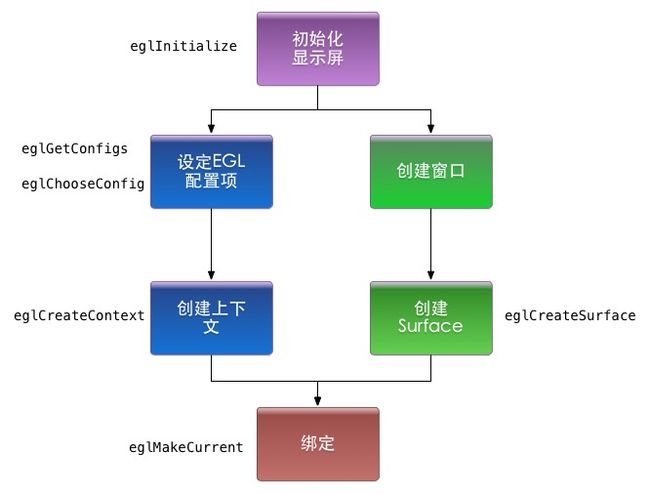
这部分工作在SurfaceFlinger::init函数完成,也即服务初起之时:
    // initialize EGL for the default display
    mEGLDisplay = eglGetDisplay(EGL_DEFAULT_DISPLAY);
    eglInitialize(mEGLDisplay, NULL, NULL);

    //初始化硬件合成器(这个和3D合成无关)
    mHwc = new HWComposer(this,
            *static_cast(this));

    //创建渲染引擎,主要是选择EGL配置,选择OpenGL版本,创建OpenGL上下文
    mRenderEngine = RenderEngine::create(mEGLDisplay, mHwc->getVisualID());
    // retrieve the EGL context that was selected/created
    mEGLContext = mRenderEngine->getEGLContext();

    LOG_ALWAYS_FATAL_IF(mEGLContext == EGL_NO_CONTEXT,
            "couldn't create EGLContext");

    //创建OpenGL的渲染目标Surface
    for (size_t i=0 ; i// set-up the displays that are already connected
        if (mHwc->isConnected(i) || type==DisplayDevice::DISPLAY_PRIMARY) {
            // All non-virtual displays are currently considered secure.
            bool isSecure = true;
            createBuiltinDisplayLocked(type);
            wp token = mBuiltinDisplays[i];

            sp producer;
            sp consumer;
            BufferQueue::createBufferQueue(&producer, &consumer,
                    new GraphicBufferAlloc());
            /*创建窗口Surface所需要的window句柄,注意这里面window句柄是FramebufferSurface*/
            sp fbs = new FramebufferSurface(*mHwc, i,
                    consumer);
            int32_t hwcId = allocateHwcDisplayId(type);
            /*在构造函数中,调用 eglCreateSurface 创建了OpenGL渲染的目标Surface*/
            sp hw = new DisplayDevice(this,
                    type, hwcId, mHwc->getFormat(hwcId), isSecure, token,
                    fbs, producer,
                    mRenderEngine->getEGLConfig());
            if (i > DisplayDevice::DISPLAY_PRIMARY) {
                // FIXME: currently we don't get blank/unblank requests
                // for displays other than the main display, so we always
                // assume a connected display is unblanked.
                ALOGD("marking display %zu as acquired/unblanked", i);
                hw->setPowerMode(HWC_POWER_MODE_NORMAL);
            }
            mDisplays.add(token, hw);
        }
    }

    // make the GLContext current so that we can create textures when creating Layers
    // (which may happens before we render something)
    /*绑定上下文和Surface,以便绘制,这一步在调用OpenGL的drawcall之前就可以,这里调一次貌似是没必要的*/
    getDefaultDisplayDevice()->makeCurrent(mEGLDisplay, mEGLContext);
注意到,创建的窗口是FramebufferSurface,在3D渲染完成后,会由eglSwapBuffers触发queueBuffer,进而触发FramebufferSurface中的onFrameAvailable方法:
void FramebufferSurface::onFrameAvailable() {
    sp buf;
    sp acquireFence;
    /*acquireBuffer,取得一块生产完成(3D合成好)的Buffer*/
    status_t err = nextBuffer(buf, acquireFence);
    if (err != NO_ERROR) {
        ALOGE("error latching nnext FramebufferSurface buffer: %s (%d)",
                strerror(-err), err);
        return;
    }
    /*最终调用 gralloc 模块中的 post方法,该此Buffer送显*/
    err = mHwc.fbPost(mDisplayType, acquireFence, buf);
    if (err != NO_ERROR) {
        ALOGE("error posting framebuffer: %d", err);
    }
}
Layer与纹理
http://blog.csdn.net/jxt1234and2010/article/details/44821227 提到,Layer对应一个GraphicBuffer队列,每次合成时是作为消费者,取其中一个GraphicBuffer参与。
把GraphicBuffer上传为纹理,再渲染是非常cost的,因此Android用的方式是共享:
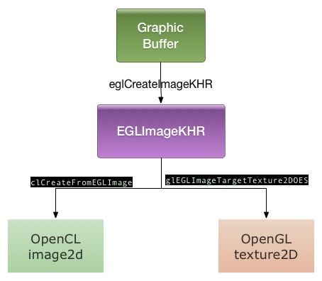
1、应用层绘制命令完成,queueBuffer回去。
2、通过binder机制,触发Layer的onFrameAvailable回调,给SurfaceFlinger消息处理线程发一个Layer更新的消息。
3、在收到Layer更新的消息后,SurfaceFlinger更新所有的dirty Layer,把GraphicBuffer映射为OpenGL的texture
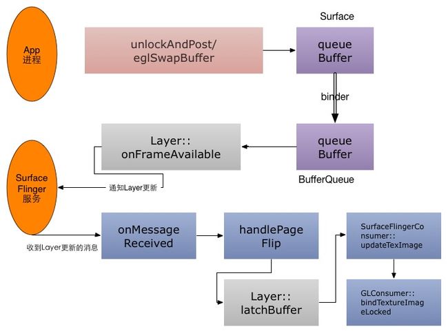
中间代码流程很复杂,我们只看下实际创建的一段:
EGLImageKHR GLConsumer::EglImage::createImage(EGLDisplay dpy,
        const sp& graphicBuffer, const Rect& crop) {
    EGLClientBuffer cbuf =
            static_cast(graphicBuffer->getNativeBuffer());
    EGLint attrs[] = {
        EGL_IMAGE_PRESERVED_KHR,        EGL_TRUE,
        EGL_IMAGE_CROP_LEFT_ANDROID,    crop.left,
        EGL_IMAGE_CROP_TOP_ANDROID,     crop.top,
        EGL_IMAGE_CROP_RIGHT_ANDROID,   crop.right,
        EGL_IMAGE_CROP_BOTTOM_ANDROID,  crop.bottom,
        EGL_NONE,
    };
    if (!crop.isValid()) {
        // No crop rect to set, so terminate the attrib array before the crop.
        attrs[2] = EGL_NONE;
    } else if (!isEglImageCroppable(crop)) {
        // The crop rect is not at the origin, so we can't set the crop on the
        // EGLImage because that's not allowed by the EGL_ANDROID_image_crop
        // extension.  In the future we can add a layered extension that
        // removes this restriction if there is hardware that can support it.
        attrs[2] = EGL_NONE;
    }
    /*此句为创建Image的代码*/
    EGLImageKHR image = eglCreateImageKHR(dpy, EGL_NO_CONTEXT,
            EGL_NATIVE_BUFFER_ANDROID, cbuf, attrs);
    if (image == EGL_NO_IMAGE_KHR) {
        EGLint error = eglGetError();
        ALOGE("error creating EGLImage: %#x", error);
    }
    return image;
}
渲染引擎
Android在此新增一个RenderEngine类,用来屏蔽OpenGL ES1.0、1.1和2.0的用法差异。基本用法和opengl是一样的,没有简化太多。
在创建RenderEngine的时候,会根据GPU所支持的OpenGL ES 版本号,优先选择 2.0,没有2.0可用时使用1.1/1.0。
class RenderEngine {
    enum GlesVersion {
        GLES_VERSION_1_0    = 0x10000,
        GLES_VERSION_1_1    = 0x10001,
        GLES_VERSION_2_0    = 0x20000,
        GLES_VERSION_3_0    = 0x30000,
    };
    static GlesVersion parseGlesVersion(const char* str);

    EGLConfig mEGLConfig;
    EGLContext mEGLContext;
    void setEGLHandles(EGLConfig config, EGLContext ctxt);

    virtual void bindImageAsFramebuffer(EGLImageKHR image, uint32_t* texName, uint32_t* fbName, uint32_t* status) = 0;
    virtual void unbindFramebuffer(uint32_t texName, uint32_t fbName) = 0;

protected:
    RenderEngine();
    virtual ~RenderEngine() = 0;

public:
    static RenderEngine* create(EGLDisplay display, int hwcFormat);

    static EGLConfig chooseEglConfig(EGLDisplay display, int format);

    // dump the extension strings. always call the base class.
    virtual void dump(String8& result);

    // helpers
    void clearWithColor(float red, float green, float blue, float alpha);
    void fillRegionWithColor(const Region& region, uint32_t height,
            float red, float green, float blue, float alpha);

    // common to all GL versions
    void setScissor(uint32_t left, uint32_t bottom, uint32_t right, uint32_t top);
    void disableScissor();
    void genTextures(size_t count, uint32_t* names);
    void deleteTextures(size_t count, uint32_t const* names);
    void readPixels(size_t l, size_t b, size_t w, size_t h, uint32_t* pixels);

    class BindImageAsFramebuffer {
        RenderEngine& mEngine;
        uint32_t mTexName, mFbName;
        uint32_t mStatus;
    public:
        BindImageAsFramebuffer(RenderEngine& engine, EGLImageKHR image);
        ~BindImageAsFramebuffer();
        int getStatus() const;
    };

    // set-up
    virtual void checkErrors() const;
    virtual void setViewportAndProjection(size_t vpw, size_t vph,
            Rect sourceCrop, size_t hwh, bool yswap, Transform::orientation_flags rotation) = 0;
    virtual void setupLayerBlending(bool premultipliedAlpha, bool opaque, int alpha) = 0;
    virtual void setupDimLayerBlending(int alpha) = 0;
    virtual void setupLayerTexturing(const Texture& texture) = 0;
    virtual void setupLayerBlackedOut() = 0;
    virtual void setupFillWithColor(float r, float g, float b, float a) = 0;

    virtual void disableTexturing() = 0;
    virtual void disableBlending() = 0;

    // drawing
    virtual void drawMesh(const Mesh& mesh) = 0;

    // grouping
    // creates a color-transform group, everything drawn in the group will be
    // transformed by the given color transform when endGroup() is called.
    virtual void beginGroup(const mat4& colorTransform) = 0;
    virtual void endGroup() = 0;

    // queries
    virtual size_t getMaxTextureSize() const = 0;
    virtual size_t getMaxViewportDims() const = 0;

    EGLConfig getEGLConfig() const;
    EGLContext getEGLContext() const;
};
Layer的绘制
在 doComposition->doDisplayComposition->doComposeSurfaces中,会让每个Layer画到每个显示屏上:
    } else {
        // we're not using h/w composer
        for (size_t i=0 ; i& layer(layers[i]);
            const Region clip(dirty.intersect(
                    tr.transform(layer->visibleRegion)));
            if (!clip.isEmpty()) {
                layer->draw(hw, clip);
            }
        }
    }
Layer::draw->Layer::onDraw->Layer::drawWithOpenGL:
void Layer::drawWithOpenGL(const sp<const DisplayDevice>& hw,
        const Region& /* clip */, bool useIdentityTransform) const {
    const State& s(getDrawingState());
    /*计算所要绘制的区域坐标*/
    computeGeometry(hw, mMesh, useIdentityTransform);

    /*计算对应的纹理坐标*/
    const Rect win(computeBounds());

    float left   = float(win.left)   / float(s.active.w);
    float top    = float(win.top)    / float(s.active.h);
    float right  = float(win.right)  / float(s.active.w);
    float bottom = float(win.bottom) / float(s.active.h);

    // TODO: we probably want to generate the texture coords with the mesh
    // here we assume that we only have 4 vertices
    Mesh::VertexArray<vec2> texCoords(mMesh.getTexCoordArray<vec2>());
    texCoords[0] = vec2(left, 1.0f - top);
    texCoords[1] = vec2(left, 1.0f - bottom);
    texCoords[2] = vec2(right, 1.0f - bottom);
    texCoords[3] = vec2(right, 1.0f - top);

    RenderEngine& engine(mFlinger->getRenderEngine());
    //这里是设定图层混合的模式(mPremultipliedAlpha表示该图层是否已经做过预乘处理,Opaque表示该图层像素是否无视本图层的透明度,s.alpha表示该图层的整体透明度)
    engine.setupLayerBlending(mPremultipliedAlpha, isOpaque(s), s.alpha);
    /*调drawCall,发送命令进行绘制*/
    engine.drawMesh(mMesh);
    engine.disableBlending();
}
OpenGL的顶点坐标(位置坐标与纹理坐标)都在 mMesh 之中,其计算方式可以仔细看看,较为繁琐,这里不讲。
硬件合成将在下篇讲述
