激光雷达的地面-非地面分割和pcl_ros实践
此文是Adam博客的案例,学习ROS过程中的一次尝试,代码已经跑通
环境
Ubuntu16.04 + ROS Kinetic
其中ROS在安装的时候选择full,安装full的话应该是把pcl相关的东西安装好了,因此在测试的时候并没有显示pcl相关的错误。
下载好完整的代码:https://download.csdn.net/download/adamshan/10696443
关于ROS-Kinetic的安装可以参考这篇博客:https://blog.csdn.net/qq_33287871/article/details/104930990
简介:
在无人驾驶的雷达感知中,将雷达点云地面分割出来是一步基本的操作,这一步操作主要能够改善地面点对于地面以上的目标的点云聚类的影响。本文首先带大家入门pcl_ros,首先我们使用pcl_ros编写一个简单的ros节点,对输入点云进行Voxel Grid Filter。接着在此实践的基础上实现点云地面和非地面的分割节点。
pcl_ros
在ROS项目中引入PCL库
首先创建一个功能包,命名为pcl_test,可以通过如下指令生成workspace和package:
cd Downloads/ROS
mkdir -p pcl_ws/src
cd pcl_ws
catkin_make
source devel/setup.bash
cd src
catkin_create_pkg pcl_test roscpp sensor_msgs pcl_ros
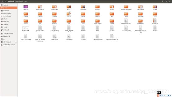
为了避免以后每次运行都需要运行一次source devel/setup.bash,可以把该工程的setup.bash文件写到环境下的.bashrc文件中,进入到Home文件夹下,摁Ctrl+H
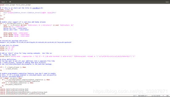
 打开.bashrc文件,将该工程的setup.bash路径写在最后一行
 这样,我们就新建了一个workspace,用于学习PCL,同时新建了一个名为pcl_test的package,这个ROS包依赖于roscpp,sensor_msgs, pcl_ros这几个包,我们修改pcl_test包下的CMakeList文件以及package.xml配置文件,如下:
package.xml 文件:
<?xml version="1.0"?>
<package>
  <name>pcl_test</name>
  <version>0.0.1</version>
  <description>The pcl_test package</description>


  <maintainer email="[email protected]">adam</maintainer>

  <license>MIT</license>


  <buildtool_depend>catkin</buildtool_depend>
  <build_depend>roscpp</build_depend>
  <build_depend>sensor_msgs</build_depend>
  <build_depend>pcl_ros</build_depend>

  <run_depend>roscpp</run_depend>
  <run_depend>sensor_msgs</run_depend>
  <run_depend>pcl_ros</run_depend>
</package>
CMakeList.txt 文件:
cmake_minimum_required(VERSION 2.8.3)
project(pcl_test)

add_compile_options(-std=c++11)


find_package(catkin REQUIRED COMPONENTS
pcl_ros
roscpp
sensor_msgs
)


catkin_package(
  INCLUDE_DIRS include
  CATKIN_DEPENDS roscpp sensor_msgs pcl_ros
)

include_directories(
 include
 ${catkin_INCLUDE_DIRS}
)
link_directories(${PCL_LIBRARY_DIRS})


add_executable(${PROJECT_NAME}_node src/pcl_test_node.cpp src/pcl_test_core.cpp)


target_link_libraries(${PROJECT_NAME}_node
  ${catkin_LIBRARIES}
  ${PCL_LIBRARIES}
)
package.xml的内容很简单,实际上就是这个包的描述文件,build_depend 和 run_depend 两个描述符分别指定了程序包编译和运行的依赖项,通常是所用到的库文件的名称。在这里我们指定了三个编译和运行时依赖项,分别是roscpp(编写C++ ROS节点),sensor_msgs(定义了激光雷达的msg),pcl_ros(连接ROS和pcl库)。
同样的,在CMakeList中,我们通过find_package查找这三个包的路径,然后将三个包添加到 CATKIN_DEPENDS, 在使用pcl库前,需要将PCL库的路径链接,通过link_directories( P C L L I B R A R Y D I R S ) 来 完 成 , 并 在 最 后 的 t a r g e t l i n k l i b r a r i e s 中 添 加 {PCL_LIBRARY_DIRS})来完成,并在最后的target_link_libraries中添加 PCLLIBRARYDIRS)来完成,并在最后的targetlinklibraries中添加{PCL_LIBRARIES}。
编写节点进行Voxel Grid Filter
接着我们在pcl_test/src目录下新建pcl_test_node.cpp文件:
#include "pcl_test_core.h"
int main(int argc, char **argv)
{
	//初始化节点,第三个参数node_nam
    ros::init(argc, argv, "pcl_test");
    //nh每个节点都对应一个句柄,实例化节点
    ros::NodeHandle nh;
    //初始化PclTestCore类,调用构造函数PclTestCore(ros::NodeHandle &nh);
    PclTestCore core(nh);
    return 0;
}
此文件仅包含main函数,是节点的入口,编写头文件include/pcl_test_core.h:
#pragma once
//导入ROS系统包含核心公共头文件
#include 以及pcl_test_core.cpp:
#include "pcl_test_core.h"
PclTestCore::PclTestCore(ros::NodeHandle &nh){
//接收到的点云的原始数据
sub_point_cloud_ = nh.subscribe("/velodyne_points",10, &PclTestCore::point_cb, this);
//滤波后的点运数据
pub_filtered_points_ = nh.advertise<sensor_msgs::PointCloud2>("/filtered_points", 10);
ros::spin();
}
PclTestCore::~PclTestCore(){}
void PclTestCore::Spin(){
}
void PclTestCore::point_cb(const sensor_msgs::PointCloud2ConstPtr & in_cloud_ptr){
//定义了两个点云指针,声明存储原始数据与滤波后的数据的点云的格式
//pcl::PointClound是原始点云的数据格式
pcl::PointCloud<pcl::PointXYZI>::Ptr current_pc_ptr(new pcl::PointCloud<pcl::PointXYZI>);
pcl::PointCloud<pcl::PointXYZI>::Ptr filtered_pc_ptr(new pcl::PointCloud<pcl::PointXYZI>);
//ros转化为pcl中的点云的数据格式,sensor_msgs::PointClound2转pcl::PointClound转sensor_msgs::PointCloud2。第一个参数是滤波后的pcl xyz格式点云,第二个参数是抓换后的ros pointcloud2格式,之后发布就发布该点云。
pub_pc.header = in_cloud_ptr->header;
pub_filtered_points_.publish(pub_pc);
}
这个节点的功能是订阅来自/velodyne_points话题的点云数据,使用PCL内置的Voxel Grid Filter对原始的点云进行降采样,将降采样的结果发布到/filtered_points话题上。我们重点看回调函数PclTestCore::point_cb,在该回调函数中,我们首先定义了两个点云指针,在PCL库中,pcl::PointCloud< T >是最基本的一种数据结构,它表示一块点云数据(点的集合),我们可以指定点的数据结构,在上述实例中,采用了pcl::PointXYZI这种类型的点。pcl::PointXYZI结构体使用(x, y, z, intensity)这四个数值来描述一个三维度空间点。
intensity,即反射强度,是指激光雷达的激光发射器发射激光后收到的反射的强度,通常所说的16线,32线激光雷达,其内部实际是并列纵排的多个激光发射器,通过电机自旋,产生360环视的点云数据,不同颜色的物体对激光的反射强度也是不同的,通常来说,白色物体的反射强度(intensity)最强,对应的,黑色的反射强度最弱。
通常使用sensor_msgs/PointCloud2.h 做为点云数据的消息格式,可使用pcl::fromROSMsg和pcl::toROSMsg将sensor_msgs::PointCloud2与pcl::PointCloud< T >进行转换。
为了使用Voxel Grid Filter对原始点云进行降采样,只需定义pcl::VocelGrid并且指定输入点云和leaf size,在本例中,我们使用leaf size为 0.2。Voxel Grid Filter将输入点云使用0.2m0.2m0.2m的立方体进行分割,使用小立方体的 形心(centroid) 来表示这个立方体的所有点,保留这些点作为降采样的输出。
验证效果
我们写一个launch文件pcl_test.launch来启动这个节点:
<launch>
    <node pkg="pcl_test" type="pcl_test_node" name="pcl_test_node" output="screen"/>
</launch>
回到工作空间路径下,使用catkin_make进行编译
catkin_make
启动这个节点
roslaunch pcl_test pcl_test.launch
打开第三个终端,启动rviz
rosrun rviz rviz -f velodyne
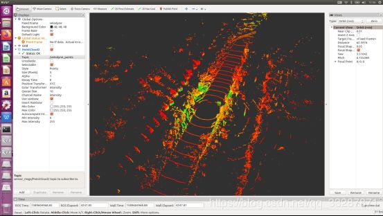
配置Rviz的Frame为velodyne,并且加载原始点云和过滤以后的点云的display

新建终端,并运行我们的测试bag(测试bag下载链接:https://pan.baidu.com/s/1HOhs9StXUmZ_5sCALgKG3w)
回到bag文件所在的路径打开一个新的终端,运行如下指令:
rosbag play --clock test.bag

降采样之后的点云(即我们的节点的输出):

【注】在此之前的操作属于pcl_ros读取bag激光雷达点云的实现
点云地面过滤
过滤地面是激光雷达感知中一步基础的预处理操作,因为我们环境感知通常只对路面上的障碍物感兴趣,且地面的点对于障碍物聚类容易产生影响,所以在做Lidar Obstacle Detection之前通常将地面点和非地面点进行分离。在此文中我们介绍一种被称为Ray Ground Filter的路面过滤方法,并且在ROS中实践。
对点云剪裁和过滤
要分割地面和非地面,那么过高的区域首先就可以忽略不计,我们先对点云进行高度的裁剪。我们实验用的bag在录制的时候lidar的高度约为1.78米,我们剪裁掉1.28米以上的部分,代码如下:
void PclTestCore::clip_above(double clip_height, const pcl::PointCloud<pcl::PointXYZI>::Ptr in,
                             const pcl::PointCloud<pcl::PointXYZI>::Ptr out)
{
    pcl::ExtractIndices<pcl::PointXYZI> cliper;

    cliper.setInputCloud(in);
    pcl::PointIndices indices;
#pragma omp for
    for (size_t i = 0; i < in->points.size(); i++)
    {
        if (in->points[i].z > clip_height)
        {
            indices.indices.push_back(i);
        }
    }
    cliper.setIndices(boost::make_shared<pcl::PointIndices>(indices));
    cliper.setNegative(true); //ture to remove the indices
    cliper.filter(*out);
}
为了消除车身自身的雷达反射的影响,我们对近距离的点云进行过滤,仍然使用pcl::ExtractIndices进行剪裁:
void PclTestCore::remove_close_pt(double min_distance, const pcl::PointCloud<pcl::PointXYZI>::Ptr in,
                                  const pcl::PointCloud<pcl::PointXYZI>::Ptr out)
{
    pcl::ExtractIndices<pcl::PointXYZI> cliper;

    cliper.setInputCloud(in);
    pcl::PointIndices indices;
#pragma omp for
    for (size_t i = 0; i < in->points.size(); i++)
    {
        double distance = sqrt(in->points[i].x*in->points[i].x + in->points[i].y*in->points[i].y);

        if (distance < min_distance)
        {
            indices.indices.push_back(i);
        }
    }
    cliper.setIndices(boost::make_shared<pcl::PointIndices>(indices));
    cliper.setNegative(true); //ture to remove the indices
    cliper.filter(*out);
}
其中,#pragma omp for语法OpenMP的并行化语法,即希望通过OpenMP并行化执行这条语句后的for循环,从而起到加速的效果。
角度微分和地面/非地面判断
Ray Ground Filter算法的核心是以射线(Ray)的形式来组织点云。我们现在将点云的 (x, y, z)三维空间降到(x,y)平面来看,计算每一个点到车辆x正方向的平面夹角 θ, 我们对360度进行微分,分成若干等份,每一份的角度为0.18度,这个微分的等份近似的可以看作一条射线,如下图所示,图中是一个激光雷达的纵截面的示意图,雷达由下至上分布多个激光器,发出如图所示的放射状激光束,这些激光束在平地上即表现为,图中的水平线即为一条射线:
0.18度是VLP32C雷达的水平光束发散间隔。
为了方便地对点进行半径和夹角的表示,我们使用如下数据结构代替pcl::PointCloudXYZI:
  struct PointXYZIRTColor
  {
    pcl::PointXYZI point;

    float radius; //cylindric coords on XY Plane
    float theta;  //angle deg on XY plane

    size_t radial_div;     //index of the radial divsion to which this point belongs to
    size_t concentric_div; //index of the concentric division to which this points belongs to

    size_t original_index; //index of this point in the source pointcloud
  };
  typedef std::vector<PointXYZIRTColor> PointCloudXYZIRTColor;
其中,radius表示点到lidar的水平距离(半径),即:
![]()
theta是点相对于车头正方向(即x方向)的夹角,计算公式为:

我们用radial_div和concentric_div分别描述角度微分和距离微分。对点云进行水平角度微分之后,可得到:360/0.18=2000条射线,将这些射线中的点按照距离的远近进行排序,如下所示:
    //将同一根射线上的点按照半径(距离)排序
#pragma omp for
    for (size_t i = 0; i < radial_dividers_num_; i++)
    {
        std::sort(out_radial_ordered_clouds[i].begin(), out_radial_ordered_clouds[i].end(),[](const PointXYZIRTColor &a, const PointXYZIRTColor &b) { return a.radius < b.radius; });
    }
通过判断射线中前后两点的坡度是否大于我们事先设定的坡度阈值,从而判断点是否为地面点。代码如下:
void PclTestCore::classify_pc(std::vector<PointCloudXYZIRTColor> &in_radial_ordered_clouds,
                              pcl::PointIndices &out_ground_indices,
                              pcl::PointIndices &out_no_ground_indices)
{
    out_ground_indices.indices.clear();
    out_no_ground_indices.indices.clear();
#pragma omp for
    for (size_t i = 0; i < in_radial_ordered_clouds.size(); i++) //sweep through each radial division 遍历每一根射线
    {
        float prev_radius = 0.f;
        float prev_height = -SENSOR_HEIGHT;
        bool prev_ground = false;
        bool current_ground = false;
        for (size_t j = 0; j < in_radial_ordered_clouds[i].size(); j++) //loop through each point in the radial div
        {
            float points_distance = in_radial_ordered_clouds[i][j].radius - prev_radius;
            float height_threshold = tan(DEG2RAD(local_max_slope_)) * points_distance;
            float current_height = in_radial_ordered_clouds[i][j].point.z;
            float general_height_threshold = tan(DEG2RAD(general_max_slope_)) * in_radial_ordered_clouds[i][j].radius;

            //for points which are very close causing the height threshold to be tiny, set a minimum value
            if (points_distance > concentric_divider_distance_ && height_threshold < min_height_threshold_)
            {
                height_threshold = min_height_threshold_;
            }

            //check current point height against the LOCAL threshold (previous point)
            if (current_height <= (prev_height + height_threshold) && current_height >= (prev_height - height_threshold))
            {
                //Check again using general geometry (radius from origin) if previous points wasn't ground
                if (!prev_ground)
                {
                    if (current_height <= (-SENSOR_HEIGHT + general_height_threshold) && current_height >= (-SENSOR_HEIGHT - general_height_threshold))
                    {
                        current_ground = true;
                    }
                    else
                    {
                        current_ground = false;
                    }
                }
                else
                {
                    current_ground = true;
                }
            }
            else
            {
                //check if previous point is too far from previous one, if so classify again
                if (points_distance > reclass_distance_threshold_ &&
                    (current_height <= (-SENSOR_HEIGHT + height_threshold) && current_height >= (-SENSOR_HEIGHT - height_threshold)))
                {
                    current_ground = true;
                }
                else
                {
                    current_ground = false;
                }
            }

            if (current_ground)
            {
                out_ground_indices.indices.push_back(in_radial_ordered_clouds[i][j].original_index);
                prev_ground = true;
            }
            else
            {
                out_no_ground_indices.indices.push_back(in_radial_ordered_clouds[i][j].original_index);
                prev_ground = false;
            }

            prev_radius = in_radial_ordered_clouds[i][j].radius;
            prev_height = in_radial_ordered_clouds[i][j].point.z;
        }
    }
}
这里有两个重要参数,一个是local_max_slope_,是我们设定的同条射线上邻近两点的坡度阈值,一个是general_max_slope_,表示整个地面的坡度阈值,这两个坡度阈值的单位为度(degree),我们通过这两个坡度阈值以及当前点的半径(到lidar的水平距离)求得高度阈值,通过判断当前点的高度(即点的z值)是否在地面加减高度阈值范围内来判断当前点是为地面。
在地面判断条件中,current_height <= (-SENSOR_HEIGHT + general_height_threshold) && current_height >= (-SENSOR_HEIGHT - general_height_threshold) 中SENSOR_HEIGHT表示lidar挂载的高度,-SNESOR_HEIGHT即表示水平地面。
分割效果
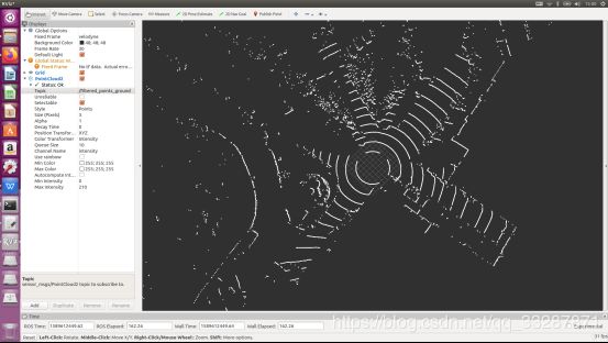
我们使用上文中的bag来验证地面分割节点的工作效果。运行bag并且运行我们的节点,打开Rviz,加载两个点云display,效果如下所示:
 参考:
参考:
https://blog.csdn.net/AdamShan/article/details/82901295
https://blog.csdn.net/sf9898/article/details/105442350