- 有关 idm 在b站不显示浮动下载条
系着秋天的落叶�
idmwindows电脑
在B站无法显示IDM(InternetDownloadManager)的浮动下载条可能是由以下几个原因导致的。以下是一些可能的解决方案:1.检查IDM的浏览器扩展是否安装并启用确保你的浏览器已经正确安装了IDM的扩展程序:Chrome/Edge:在浏览器地址栏输入chrome://extensions/或edge://extensions/,检查IDM扩展是否启用。Firefox:在about:a
- 基于ensp企业/校园规划网络方案,包含(论文 ppt 毕设实验拓扑 开题报告 知网查重)网络工程计算机网络技术毕业设计 ensp网络规划设计 校园/企业网络规划网络构建 ensp毕业设计 论文+拓扑
毕设论文+hal2651
ensp网络工程网路规划设计网络课程设计计算机网络
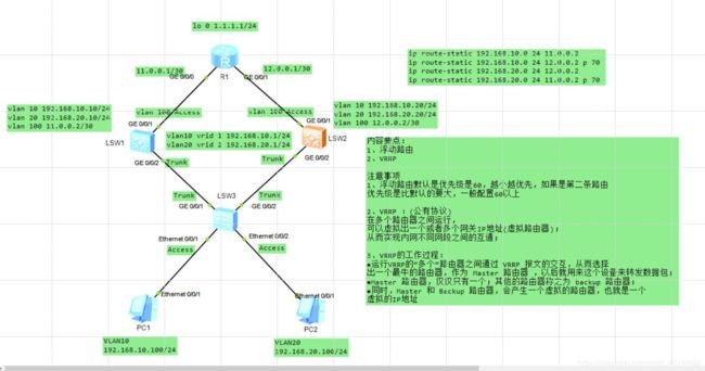
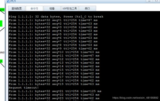
目录摘要可定制实验毕设拓扑实验文档包查重私信作者获取完整内容引言第一章网络设计与原则1.1网络设计原则1.2系统设计原则1.3网络系统设计目标第二章需求分析2.1用户需求2.2网络功能需求2.3网络拓扑需求2.4网络安全需求第三章网络规划设计3.1总体设计3.2功能设计3.3网络安全设计3.4公司网络设计3.5ip地址和vlan划分3.6设备选型第四章网络设计4.1链路聚合配置4.2vrrp配置4
- Qt的QDockWidget 样式设置详细指南(涵盖标题栏、边框、浮动状态等)
水瓶丫头站住
样式表Qtqt开发语言
以下是关于QDockWidget样式设置的详细指南,涵盖标题栏、边框、浮动状态等常见定制需求:1.核心样式属性QDockWidget的样式可通过以下选择器和子控件控制:QDockWidget:主容器样式QDockWidget::title:标题栏区域QDockWidget::close-button和QDockWidget::float-button:关闭/浮动按钮QDockWidget:floa
- 大学生HTML期末大作业——HTML+CSS+JavaScript学校网站(成都大学)
无·糖
Web前端期末大作业html课程设计css大学生前端javascript大学生大作业
HTML+CSS+JS【学校网站】网页设计期末课程大作业web前端开发技术web课程设计网页规划与设计文章目录一、网站题目二、网站描述三、网站介绍四、网站效果五、️网站代码六、️如何学习进步七、☠️更多干货文章目录一、网站题目学校网站(成都大学)6页含JQ二、网站描述总结了一些学生网页制作的经验:一般的网页需要融入以下知识点:div+css布局、浮动、定位、高级css、表格、表单及验证、js轮
- HTML5、CSS3面试题
Xu.Youth
大数据
目录1、说一说H5新标签?2、CSS3的新特性?3、如何实现一个盒子水平垂直居中?4、你是怎么理解BFC的?5、说一说盒子模型?6、如何画一个三角形?7、说一些块级元素和行内元素8、简单聊一聊重排和回流?9、文本超出部分显示省略号?10、说一说清除浮动的方式?11、请你说一说css的选择器,以及优先级12、来说一说CSS3的过渡?13、简单聊一聊CSS3的2D、3D转换14、说一说CSS3的动画?
- 网络运维学习笔记 009网工初级(HCIA-Datacom与CCNA-EI)STP生成树协议与VRRP虚拟路由冗余协议
技术小齐
网络运维学习
文章目录STP(SpanningTreeProtocol,生成树协议)思科:华为:实验思科华为VRRP(VirtualRouterRedundancyProtocol,虚拟路由冗余协议)思科华为STP(SpanningTreeProtocol,生成树协议)提高可靠性(使用冗余链路)的同时避免环路产生的问题(广播风暴,MAC地址表震荡)。STP模式有三种:MSTP(默认,而且常用)、RSTP、STP
- 关于SNAT、DNAT及浮动地址
roshy
运维
SNAT、DNATSNAT、DNAT就是实现代理的功能。SNAT类似于客户端代理:内网主机通过共享公网IP地址访问外部服务。DNAT类似于服务端代理:外部请求通过公网IP转发到内网主机上的服务。没有大网地址的内部主机想要作为客户端访问外部网络(主机)就用SNAT,如公司、家庭主机上网。没有大网地址的内部主机想要作为服务端被外部访问就用DNAT。SNAT(源地址转换)和DNAT(目的地址转换)都是N
- HCIE LAB战报(附实验环境)
若时光安好
数通HCIE交换与路由技术网络运维网络通信
考试时间:2020.9.28考点:北京华为培训中心考题:TS:Option-A,链路聚合,MSTP,MUX-VLAN,BGP控制,OSPFV3,VRRP,VRRPV3,sham-link,telnet.TAC:AR32无法访问AR28的loopback0。LAB:LAB2总体的考试和平时练习的差不多,平时练习两个不同机构的TS版本,加起来涵盖了所有错点。但是考试时TS里留了一些坑,比如平时练习的是
- CSS 性能优化全攻略:提升网站加载速度与流畅度
吴师兄大模型
css前端CSS性能优化htmlCSS3HTML性能优化
系列文章目录01-从零开始学CSS选择器:属性选择器与伪类选择器完全指南02-避免样式冲突:掌握CSS选择器优先级与层叠规则的终极指南03-如何精确掌控网页布局?深入解析CSS样式与盒模型04-CSS布局全面解析:从传统浮动到现代Flexbox和Grid05-从基础到进阶,掌握CSS变量与calc()函数的完整指南06-CSS进阶技巧:动态效果与主题切换让你的网页焕然一新07-掌握CSSFlexb
- 响应式设计实战指南:适配各种设备和浏览器
吴师兄大模型
css前端HTML响应式设计浏览器适配设备适配CSS3
系列文章目录01-从零开始学CSS选择器:属性选择器与伪类选择器完全指南02-避免样式冲突:掌握CSS选择器优先级与层叠规则的终极指南03-如何精确掌控网页布局?深入解析CSS样式与盒模型04-CSS布局全面解析:从传统浮动到现代Flexbox和Grid05-从基础到进阶,掌握CSS变量与calc()函数的完整指南06-CSS进阶技巧:动态效果与主题切换让你的网页焕然一新07-掌握CSSFlexb
- css盒子模型与盒模型的浮动
三岁九年
csscsshtml
CSS盒子1.盒子2.内边距3.边框4.margin外边距5.父子盒模型6.外边距塌陷7.嵌套盒子的外边距塌陷8.盒模型9.标准文档流行内块元素1.行内块元素与块级元素2.按显示分类3.浮动4.脱标5.字体围绕效果6.收缩7.浮动的嵌套1.盒子盒子:容器盒子模型英文:boxmodel。最常见的盒子是divspan盒子中的区域:content宽widthpxcontent高heightcontent
- HTML--CSS盒子模型
祎2祎
htmlcss前端
一,盒子模型CSS就三个大模块:盒子模型、浮动、定位1.盒子模型所谓盒子模型:就是把HTML页面中的布局元素看作是一个矩形的盒子,也就是一个盛装内容的容器。CSS盒模型本质上是一个盒子,封装周围的HTML元素,它包括:content(内容width/height)padding(内边距)boder(边框)margin(外边距).con{width:200px;height:150px;paddin
- CSS(盒子模型三,浮动)
小小fw
csscss3html
浮动(float)浮动是一种布局手段,会使元素脱离文档流元素在文档流的时候,会分块元素,行内元素,行内块元素,各自都有一定的特点设置元素浮动,可以用float样式可选值:none默认值,不浮动left向左浮动right向右浮动设置浮动后的一些特点:(第一类特点)1、设置元素浮动后,元素会脱离文档流,就不会再占据原来在文档流的位置浮动元素后面的元素就向上2、设置元素浮动后,元素会尽可能向左或者向右浮
- CSS中的盒子模型和定位
「已注销」
前端设计基础css
目录一、盒子模型(BoxModel)1、盒子的组成2、浅析盒子模型的CSS属性二、定位(Positioning)1、了解浮动2、块级格式化上下文BFC(BlockFormatingContext)3、了解定位一、盒子模型(BoxModel)盒子模型如果我们用CSS进行网页布局时,不可避免地会碰到盒子模型。如果把网页比作一个容器,那么HTML元素(element)就是一个个的盒子,盒子里装的就是HT
- css基础之盒子模型、浮动问题
Magic.462
css前端
盒子模型一、盒子模型的组成border边框、content内容、padding内边距、margin外边距(与另外盒子的距离)1.边框border-widthborder-style:solid实线border-style:dashed虚线border-style:dotted点线border-colorborder:1pxxsolidpink;复合写法,无顺序border-top上边框border
- 前端程序员需要掌握的知识
肘击鸣的百k路
前端
一、基础技术HTML/CSS:HTML:熟练掌握各种HTML标签及其语义,能够构建结构清晰、语义明确的网页结构。了解HTML5的新特性,如语义化标签、视频音频播放、Canvas绘图等。CSS:精通CSS的语法和各种属性,能够实现丰富的页面样式。掌握CSS布局技术,包括传统的盒模型布局、浮动布局、定位布局,以及现代的Flexbox和Grid布局。熟悉CSS预处理器如Sass或Less,提高开发效率。
- Linux防护与群集第七到九章
琴剑诗酒
linux
一、keepalive作用1.支持故障自动切换2.支持健康检查3.专为lvs和ha设计的健康检查工具二.vrrp:虚拟路由冗余协议1.hsrp:cisco私有2.vrrp:公有工作在网路层三、keepalived配置1.主从:除router_id、state、priority其余都一样2.主:master备用:backuppost与get区别get:1.内容直接附着在url中2.适合传输表单内容少
- web前端必做笔试题-HTML/CSS篇
万息集训教育
html面试css3
HTML/CSS1、什么是盒子模型?请画出盒模型示意图2、行内元素有哪些?块级元素有哪些?空(void)元素有哪些?3、如何居中一个div?如何居中一个浮动元素?(多种方式)4、什么是cssHack?5、css选择器有哪些?优先级是怎样的?6、你做的页面在哪些浏览器测试过?这些浏览器的内核分别是什么?7、什么是外边距重叠?重叠的结果是什么?8、Rgba()和opacity的透明效果有什么不同?9、
- Vue.js组件开发-实现字母向上浮动
LCG元
前端vue.js前端javascript
使用Vue实现字母向上浮动的效果实现步骤创建Vue项目:使用VueCLI来创建一个新的Vue项目。定义组件结构:在组件的模板中,定义包含字母的元素。添加样式:使用CSS动画来实现字母向上浮动的效果。绑定动画类:在Vue组件中,为字母元素绑定动画类。完整代码{{letter}}exportdefault{data(){return{//要显示的字母字符串text:"Hello,World!",//将
- Vue.js组件开发-实现底部浮动导航页面滚动预览
LCG元
前端vue.jsjavascript前端
使用Vue实现底部浮动导航,并且在页面滚动时进行预览步骤概述创建Vue项目:使用VueCLI创建一个新的Vue项目。设计页面结构:创建包含内容区域和底部浮动导航栏的页面结构。实现滚动监听:监听页面滚动事件,根据滚动位置更新导航栏的激活状态。实现导航跳转:点击导航栏的项时,页面滚动到相应的内容区域。详细代码1.创建Vue项目安装VueCLI,可以使用以下命令进行安装:npminstall-g@vue
- 前端总结——HTML + CSS
巴拉巴拉巴7788
csshtml前端
文章目录一、HTML+CSS1.讲一下盒模型,普通盒模型和怪异盒模型有什么区别?2.块元素和行内元素区别是什么?常见块元素和行内元素有哪些?3.HTML语义化标签有哪些?4.伪类和伪元素的区别是什么?5.CSS如何实现垂直居中?6.CSS常见的选择器有哪些?7.CSS的优先级如何计算?8.长度单位px、em和rem的区别是什么?9.讲一下flex弹性盒布局?10.浮动塌陷问题解决方法是什么?11.
- 前端八股(1)html,css,js,es6
shadowflies
前端八股前端面试html5css3javascriptes6
跟着视频捋八股,效果还是可以的,就是得需要先有基础才能听得懂讲啥以下是一些八股记录(简单版),可以帮助记忆关键词,从而后续自己拓展目录一、CSS1.说一下css的盒模型2.csS选择器的优先级?3.隐藏元素的方法有哪些?4.px和rem的区别是什么?5.重绘重排有什么区别?6.让一个元素水平垂直居中的方式有哪些?7.css的哪些属性哪些可以继承?哪些不可以继承?8.有没有用过预处理器?9.清除浮动
- Vue.js组件开发-实现右下角浮动层可以最大化最小化效果
LCG元
前端vue.js前端javascript
使用Vue实现右下角浮动层可以最大化最小化效果实现步骤创建Vue项目:使用VueCLI来创建一个新的Vue项目。设计浮动层组件:在组件中定义浮动层的样式和布局,包括最大化、最小化按钮。实现最大化和最小化功能:通过数据绑定和事件处理来控制浮动层的显示和隐藏。定位浮动层:将浮动层定位到页面的右下角。代码实现1.创建Vue项目安装VueCLI,可以使用以下命令进行安装:npminstall-g@vue/
- Vue和Vue-Element-Admin(十):HTML和CSS快速学习笔记
A叶子叶
#Vue与Web开发vue.jshtmlcss
目录html标签分类网页布局盒子模型浮动定位css标签选择flex布局transform转换Vue开发tipsless和scssVScode常用插件后端语言框架很多,Java适合企业级应用(规范且稳定),Go适合高并发场景(比如云上产品),Python框架(bottle,tornado,django)简单且快速,也天然适合数据分析场景,PHP适合快速建站,前端变化小,所见即所得,因此抽空记录下学习
- Vue.js组件开发-实现图片浮动效果
LCG元
前端vue.js前端javascript
使用Vue实现图片浮动效果实现思路将使用Vue的单文件组件(.vue)来实现图片浮动效果。主要思路是通过CSS的transform属性结合JavaScript的定时器来改变图片的位置,从而实现浮动效果。代码实现exportdefault{data(){return{//初始化图片在x轴上的偏移量xOffset:0,//初始化图片在y轴上的偏移量yOffset:0,//定时器ID,用于后续清除定时器
- 大学生HTML期末大作业——HTML+CSS+JavaScript美食网站(西餐)
无·糖
Web前端期末大作业html课程设计css大学生javascript美食大作业
HTML+CSS+JS【美食网站】网页设计期末课程大作业web前端开发技术web课程设计网页规划与设计文章目录一、网站题目二、网站描述三、网站介绍四、网站效果五、️网站代码六、️如何学习进步七、☠️更多干货文章目录一、网站题目美食网站(西餐)精美响应式含JQuery7页二、网站描述总结了一些学生网页制作的经验:一般的网页需要融入以下知识点:div+css布局、浮动、定位、高级css、表格、表单
- 科技快讯 | 领英“隐私风波”告一段落;华为余承东智驾 1345 公里返工,称智界 R7 打赢“鸡蛋保卫战”;谷歌翻译将增“提问”功能
最新科技快讯
科技
谷歌安卓16快捷设置被曝告别悬浮窗,选项在面板内展开科技媒体AndroidAuthority于1月30日发布博文,称谷歌安卓16更新中,快捷面板(QuickSetting)功能可能回归旧版样式。当前安卓版QuickSetting点击磁贴会扩展为浮动面板,而安卓16可能会让磁贴扩展并填满整个面板,提供更多信息。旧版Android系统(至Android9)都采用这种设计。ASML即将发货首台第二代Hi
- 两栏布局、三栏布局、水平垂直居中
子非鱼921
前端面试css前端javascript
文章目录1两栏布局1.1浮动+margin1.2浮动+BFC1.3flex布局1.4左绝父相+margin1.5右绝父相+方向定位2三栏布局2.1子绝父相+margin2.2flex布局2.3浮动+margin2.4圣杯布局2.5双飞翼布局3水平垂直居中3.1绝对定位+translate3.2绝对定位+margin3.3绝对定位+margin3.4flex布局1两栏布局一般两栏布局指的是左边一栏宽
- CSS布局和定位应用方案
天涯学馆
大前端&移动端全栈架构css前端
目录浮动布局绝对布局表格布局响应式布局弹性布局网格布局多栏布局浮动布局CSS3浮动布局的核心在于使用float属性将元素移出文档流,通过左右浮动来排列元素,并结合clear属性或清除浮动技巧(如这里的伪元素法)来处理浮动带来的副作用。尽管浮动布局在某些简单布局中依然实用,但对于更复杂的布局需求&#
- 17、智能驾驶硬件架构安全设计一般原则
OEM的牛马DRE
智能驾驶控制器硬件介绍人工智能
这段文字详细描述了硬件安全架构设计的一系列要求和原则,涵盖了从基本设计原则到具体实现细节和验证要求:一、基本设计原则平衡冗余与复杂度:硬件安全架构需平衡硬件冗余设计和故障检测回路以提高容错能力,同时降低硬件复杂度以避免复杂接口和系统失效。二、硬件容错设计覆盖的故障类型内部器件故障:包括恒态和瞬态故障。外部接口故障:涉及数字IO、模拟AD、网络接口和其他总线接口。外部环境干扰:电压浮动、EMC、振动
- ASM系列五 利用TreeApi 解析生成Class
lijingyao8206
ASM字节码动态生成ClassNodeTreeAPI
前面CoreApi的介绍部分基本涵盖了ASMCore包下面的主要API及功能,其中还有一部分关于MetaData的解析和生成就不再赘述。这篇开始介绍ASM另一部分主要的Api。TreeApi。这一部分源码是关联的asm-tree-5.0.4的版本。
在介绍前,先要知道一点, Tree工程的接口基本可以完
- 链表树——复合数据结构应用实例
bardo
数据结构树型结构表结构设计链表菜单排序
我们清楚:数据库设计中,表结构设计的好坏,直接影响程序的复杂度。所以,本文就无限级分类(目录)树与链表的复合在表设计中的应用进行探讨。当然,什么是树,什么是链表,这里不作介绍。有兴趣可以去看相关的教材。
需求简介:
经常遇到这样的需求,我们希望能将保存在数据库中的树结构能够按确定的顺序读出来。比如,多级菜单、组织结构、商品分类。更具体的,我们希望某个二级菜单在这一级别中就是第一个。虽然它是最后
- 为啥要用位运算代替取模呢
chenchao051
位运算哈希汇编
在hash中查找key的时候,经常会发现用&取代%,先看两段代码吧,
JDK6中的HashMap中的indexFor方法:
/**
* Returns index for hash code h.
*/
static int indexFor(int h, int length) {
- 最近的情况
麦田的设计者
生活感悟计划软考想
今天是2015年4月27号
整理一下最近的思绪以及要完成的任务
1、最近在驾校科目二练车,每周四天,练三周。其实做什么都要用心,追求合理的途径解决。为
- PHP去掉字符串中最后一个字符的方法
IT独行者
PHP字符串
今天在PHP项目开发中遇到一个需求,去掉字符串中的最后一个字符 原字符串1,2,3,4,5,6, 去掉最后一个字符",",最终结果为1,2,3,4,5,6 代码如下:
$str = "1,2,3,4,5,6,";
$newstr = substr($str,0,strlen($str)-1);
echo $newstr;
- hadoop在linux上单机安装过程
_wy_
linuxhadoop
1、安装JDK
jdk版本最好是1.6以上,可以使用执行命令java -version查看当前JAVA版本号,如果报命令不存在或版本比较低,则需要安装一个高版本的JDK,并在/etc/profile的文件末尾,根据本机JDK实际的安装位置加上以下几行:
export JAVA_HOME=/usr/java/jdk1.7.0_25
- JAVA进阶----分布式事务的一种简单处理方法
无量
多系统交互分布式事务
每个方法都是原子操作:
提供第三方服务的系统,要同时提供执行方法和对应的回滚方法
A系统调用B,C,D系统完成分布式事务
=========执行开始========
A.aa();
try {
B.bb();
} catch(Exception e) {
A.rollbackAa();
}
try {
C.cc();
} catch(Excep
- 安墨移动广 告:移动DSP厚积薄发 引领未来广 告业发展命脉
矮蛋蛋
hadoop互联网
“谁掌握了强大的DSP技术,谁将引领未来的广 告行业发展命脉。”2014年,移动广 告行业的热点非移动DSP莫属。各个圈子都在纷纷谈论,认为移动DSP是行业突破点,一时间许多移动广 告联盟风起云涌,竞相推出专属移动DSP产品。
到底什么是移动DSP呢?
DSP(Demand-SidePlatform),就是需求方平台,为解决广 告主投放的各种需求,真正实现人群定位的精准广
- myelipse设置
alafqq
IP
在一个项目的完整的生命周期中,其维护费用,往往是其开发费用的数倍。因此项目的可维护性、可复用性是衡量一个项目好坏的关键。而注释则是可维护性中必不可少的一环。
注释模板导入步骤
安装方法:
打开eclipse/myeclipse
选择 window-->Preferences-->JAVA-->Code-->Code
- java数组
百合不是茶
java数组
java数组的 声明 创建 初始化; java支持C语言
数组中的每个数都有唯一的一个下标
一维数组的定义 声明: int[] a = new int[3];声明数组中有三个数int[3]
int[] a 中有三个数,下标从0开始,可以同过for来遍历数组中的数
- javascript读取表单数据
bijian1013
JavaScript
利用javascript读取表单数据,可以利用以下三种方法获取:
1、通过表单ID属性:var a = document.getElementByIdx_x_x("id");
2、通过表单名称属性:var b = document.getElementsByName("name");
3、直接通过表单名字获取:var c = form.content.
- 探索JUnit4扩展:使用Theory
bijian1013
javaJUnitTheory
理论机制(Theory)
一.为什么要引用理论机制(Theory)
当今软件开发中,测试驱动开发(TDD — Test-driven development)越发流行。为什么 TDD 会如此流行呢?因为它确实拥有很多优点,它允许开发人员通过简单的例子来指定和表明他们代码的行为意图。
TDD 的优点:
&nb
- [Spring Data Mongo一]Spring Mongo Template操作MongoDB
bit1129
template
什么是Spring Data Mongo
Spring Data MongoDB项目对访问MongoDB的Java客户端API进行了封装,这种封装类似于Spring封装Hibernate和JDBC而提供的HibernateTemplate和JDBCTemplate,主要能力包括
1. 封装客户端跟MongoDB的链接管理
2. 文档-对象映射,通过注解:@Document(collectio
- 【Kafka八】Zookeeper上关于Kafka的配置信息
bit1129
zookeeper
问题:
1. Kafka的哪些信息记录在Zookeeper中 2. Consumer Group消费的每个Partition的Offset信息存放在什么位置
3. Topic的每个Partition存放在哪个Broker上的信息存放在哪里
4. Producer跟Zookeeper究竟有没有关系?没有关系!!!
//consumers、config、brokers、cont
- java OOM内存异常的四种类型及异常与解决方案
ronin47
java OOM 内存异常
OOM异常的四种类型:
一: StackOverflowError :通常因为递归函数引起(死递归,递归太深)。-Xss 128k 一般够用。
二: out Of memory: PermGen Space:通常是动态类大多,比如web 服务器自动更新部署时引起。-Xmx
- java-实现链表反转-递归和非递归实现
bylijinnan
java
20120422更新:
对链表中部分节点进行反转操作,这些节点相隔k个:
0->1->2->3->4->5->6->7->8->9
k=2
8->1->6->3->4->5->2->7->0->9
注意1 3 5 7 9 位置是不变的。
解法:
将链表拆成两部分:
a.0-&
- Netty源码学习-DelimiterBasedFrameDecoder
bylijinnan
javanetty
看DelimiterBasedFrameDecoder的API,有举例:
接收到的ChannelBuffer如下:
+--------------+
| ABC\nDEF\r\n |
+--------------+
经过DelimiterBasedFrameDecoder(Delimiters.lineDelimiter())之后,得到:
+-----+----
- linux的一些命令 -查看cc攻击-网口ip统计等
hotsunshine
linux
Linux判断CC攻击命令详解
2011年12月23日 ⁄ 安全 ⁄ 暂无评论
查看所有80端口的连接数
netstat -nat|grep -i '80'|wc -l
对连接的IP按连接数量进行排序
netstat -ntu | awk '{print $5}' | cut -d: -f1 | sort | uniq -c | sort -n
查看TCP连接状态
n
- Spring获取SessionFactory
ctrain
sessionFactory
String sql = "select sysdate from dual";
WebApplicationContext wac = ContextLoader.getCurrentWebApplicationContext();
String[] names = wac.getBeanDefinitionNames();
for(int i=0; i&
- Hive几种导出数据方式
daizj
hive数据导出
Hive几种导出数据方式
1.拷贝文件
如果数据文件恰好是用户需要的格式,那么只需要拷贝文件或文件夹就可以。
hadoop fs –cp source_path target_path
2.导出到本地文件系统
--不能使用insert into local directory来导出数据,会报错
--只能使用
- 编程之美
dcj3sjt126com
编程PHP重构
我个人的 PHP 编程经验中,递归调用常常与静态变量使用。静态变量的含义可以参考 PHP 手册。希望下面的代码,会更有利于对递归以及静态变量的理解
header("Content-type: text/plain");
function static_function () {
static $i = 0;
if ($i++ < 1
- Android保存用户名和密码
dcj3sjt126com
android
转自:http://www.2cto.com/kf/201401/272336.html
我们不管在开发一个项目或者使用别人的项目,都有用户登录功能,为了让用户的体验效果更好,我们通常会做一个功能,叫做保存用户,这样做的目地就是为了让用户下一次再使用该程序不会重新输入用户名和密码,这里我使用3种方式来存储用户名和密码
1、通过普通 的txt文本存储
2、通过properties属性文件进行存
- Oracle 复习笔记之同义词
eksliang
Oracle 同义词Oracle synonym
转载请出自出处:http://eksliang.iteye.com/blog/2098861
1.什么是同义词
同义词是现有模式对象的一个别名。
概念性的东西,什么是模式呢?创建一个用户,就相应的创建了 一个模式。模式是指数据库对象,是对用户所创建的数据对象的总称。模式对象包括表、视图、索引、同义词、序列、过
- Ajax案例
gongmeitao
Ajaxjsp
数据库采用Sql Server2005
项目名称为:Ajax_Demo
1.com.demo.conn包
package com.demo.conn;
import java.sql.Connection;import java.sql.DriverManager;import java.sql.SQLException;
//获取数据库连接的类public class DBConnec
- ASP.NET中Request.RawUrl、Request.Url的区别
hvt
.netWebC#asp.nethovertree
如果访问的地址是:http://h.keleyi.com/guestbook/addmessage.aspx?key=hovertree%3C&n=myslider#zonemenu那么Request.Url.ToString() 的值是:http://h.keleyi.com/guestbook/addmessage.aspx?key=hovertree<&
- SVG 教程 (七)SVG 实例,SVG 参考手册
天梯梦
svg
SVG 实例 在线实例
下面的例子是把SVG代码直接嵌入到HTML代码中。
谷歌Chrome,火狐,Internet Explorer9,和Safari都支持。
注意:下面的例子将不会在Opera运行,即使Opera支持SVG - 它也不支持SVG在HTML代码中直接使用。 SVG 实例
SVG基本形状
一个圆
矩形
不透明矩形
一个矩形不透明2
一个带圆角矩
- 事务管理
luyulong
javaspring编程事务
事物管理
spring事物的好处
为不同的事物API提供了一致的编程模型
支持声明式事务管理
提供比大多数事务API更简单更易于使用的编程式事务管理API
整合spring的各种数据访问抽象
TransactionDefinition
定义了事务策略
int getIsolationLevel()得到当前事务的隔离级别
READ_COMMITTED
- 基础数据结构和算法十一:Red-black binary search tree
sunwinner
AlgorithmRed-black
The insertion algorithm for 2-3 trees just described is not difficult to understand; now, we will see that it is also not difficult to implement. We will consider a simple representation known
- centos同步时间
stunizhengjia
linux集群同步时间
做了集群,时间的同步就显得非常必要了。 以下是查到的如何做时间同步。 在CentOS 5不再区分客户端和服务器,只要配置了NTP,它就会提供NTP服务。 1)确认已经ntp程序包: # yum install ntp 2)配置时间源(默认就行,不需要修改) # vi /etc/ntp.conf server pool.ntp.o
- ITeye 9月技术图书有奖试读获奖名单公布
ITeye管理员
ITeye
ITeye携手博文视点举办的9月技术图书有奖试读活动已圆满结束,非常感谢广大用户对本次活动的关注与参与。 9月试读活动回顾:http://webmaster.iteye.com/blog/2118112本次技术图书试读活动的优秀奖获奖名单及相应作品如下(优秀文章有很多,但名额有限,没获奖并不代表不优秀):
《NFC:Arduino、Andro