4.8 IFFT/FFT
4.8.1 IFFT/FFT原理

1. IFFT、FFT在OFDM系统中的应用
![]()

2、IFFT/FFT原理

 3、DIT的基2FFT算法


 4、DIF的基2FFT运算

 5、基于
5、基于![]() 的频率抽选FFT算法
的频率抽选FFT算法


4.8.2 基于![]() DIF FFT的硬件 结构
DIF FFT的硬件 结构

1、各级的蝶形运算硬件实现
2、transfer12、 transfer34、transfer56硬件实现

3、transfer23、 transfer45硬件实现

4.8.3 运用IP Core实现IFFT/FFT


matlab
matlab:
function [data_out]=ifft_64(data_in,NumCarrier)
%ifft变换
%data_in为经过bpsk,qpsk,QAM16,QAM64星座映射后的复数信号
%NumCarrier为子载波数量,也即ifft变换长度
LengthSymbol=length(data_in)/NumCarrier;
data_out=zeros(1,length(data_in));
%IFFT处理,ifft函数将进行除以NumCarrier,也即64的因子
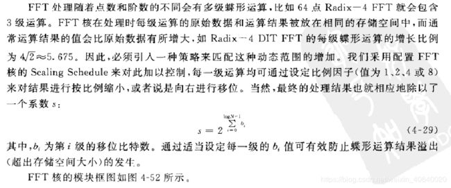
%根据硬件设计,ifft的系统缩放比例应设为2+3+2-3位为最好,三级蝶形运算,分别右移2/3/2位,然后为了不影响DAC精度,对输入信号放大左移3位
%故我们对ifft进行6-(2+3+2-3)=2,也即乘以4的处理,得到的幅值刚好在-1---1区间//???
for k=1:LengthSymbol
data_out((k-1)*NumCarrier+1:k*NumCarrier)=ifft(data_in((k-1)*NumCarrier+1:k*NumCarrier))*4;
end暂时不太会用;其实不用看,后来发现变换过程中数据会或多或少丢失,因为matalb采用的是浮点运算,fpga采用的是定点运算测试方案采用:fpgaIFFT变换后的数据,与原数据matlab仿真数据的对比,下面是程序:
时钟模块clk20M-clk60M:
//clk20M-clk60M
module change60(clk20M,clk60M,reset,inEn,outEn,dataInR,dataInI,dataOutR,dataOutI,FFT_set);
  input clk20M;
  input clk60M;
  input reset;
  input inEn;
  input [7:0]dataInR;
  input [7:0]dataInI;

  output outEn;
  output [7:0]dataOutR;
  output [7:0]dataOutI;
  output FFT_set;

  wire [7:0]dataOutR;
  wire [7:0]dataOutI;
  reg [7:0]dataInR_buf;
  reg [7:0]dataInI_buf;

  reg  En;
  wire clk60M;


always @(posedge clk20M or negedge reset)
  begin
    if(!reset)
	  	begin
		  En<=0;
		  dataInR_buf<=0;
		  dataInI_buf<=0;
		end
	 else
	   begin
	        if(inEn)
			    begin
				    dataInR_buf<=dataInR;
					dataInI_buf<=dataInI;
					En<=1;
				 end
			  else
			    begin
			        dataInR_buf<=8'b0;
					dataInI_buf<=8'b0;
				    En<=0;
				 end
		end
  end

reg mode;
reg [7:0] k;
//以clk20M的写信号
always @(posedge clk20M or negedge reset)
  begin
    if(!reset)
	   begin
	     k<=0;
	   end
	 else
	 begin
	       if(En)
			   begin
			     if(k==63)
				    k<=0;
				  else
				    k<=k+1;
				end
			end
	end

reg [7:0] r;
reg outEn;
reg FFT_set;
reg [7:0] t;

//以clk60M的读信号
always @(posedge clk60M or negedge reset)
 begin
   if(!reset)
	  begin
	     r<=0;
		 mode<=0;
		 FFT_set<=0;
		 outEn<=0;
		 t<=0;

	  end
	else begin
	       if(En)
			    begin
				   if(r==8'b10111010)
					       begin
							   FFT_set<=1;   // output FFT_set 6 clock cycle before dataOut
								r<=r+1;
							 end
					else if(r==8'b10111100)
					       begin
							   outEn<=1;   //output outEn 4 clock cycle before dataOut
								r<=r+1;
							 end
					else if(r==8'd191)
					       begin
							   mode<=1;
							   r<=0;
							 end
					else begin
					       r<=r+1;
							 FFT_set<=0;
							 outEn<=0;
						  end
				 end
			 else r<=0;
			 if(mode)
			    begin
	            if(t==63)
			         begin
						  t<=0;
						  mode<=0;
						end
			      else t<=t+1;
				 end
		  end
 end
 //实部
 rami ramr (    //BRAM for real part: input 20MHz, output 60MHz, depth 64 bytes
    .a(k),
    .dpra(t),
    .clk(clk20M),
    .qdpo_clk(clk60M),
    .d (dataInR_buf),
    .qdpo(dataOutR),
    .qdpo_ce(mode),
    .we(En));

 //虚部
 rami rami (    //BRAM for image part: input 20MHz, output 60MHz, depth 64 bytes
    .a(k),
    .dpra(t),
    .clk(clk20M),
    .qdpo_clk(clk60M),
    .d (dataInI_buf),
    .qdpo(dataOutI),
    .qdpo_ce(mode),
    .we(En));
endmodule
时钟模块的测试:
 for (j=0;j<=3;j=j+1)
    begin
    #200
    inEn=1;
        for (i=0;i<64;i=i+1)
            begin
              #54
              dataInR = {$random}%8;
              dataInI = {$random}%8;
            end
        i=0;
        inEn=0;
    end
    j=0;
时钟模块的波形:

change_60:

从现在看来完全正确:但是下一级IFFT IP的复位、开始时钟时序不太明白;继续做。。。

左移三位,八倍的关系;
先做一下原数据与原数据*3后傅里叶变换的对比:
原数据:实部:0 0 1 1 2 2 3 3 4 4 5 5 6 6 7 7 7 7 6 6 5 5 4 4 3 3 2 2 1 1 0 0
0 0 1 1 2 2 3 3 4 4 5 5 6 6 7 7 7 7 6 6 5 5 4 4 3 3 2 2 1 1 0 0
虚部:0
扩大三倍后输出的数据:
xk_re:0 0 0 0 0 0 0 0 0 0 0 0 0 0 0 0 0 0 0 0 0 0 0 0 0 0 0 0 0 0 0 0 -788 -3 -24 2 -52 -11 -19 -2 -2 -19 -11 -52 2 -24 -3 -788 0 0 0 0 0 0 0 0 0 0 0 0 0 0 0 0
xk_im:0 0 0 0 0 0 0 0 0 0 0 0 0 0 0 0 0 0 0 0 0 0 0 0 0 0 0 0 0 0 0 0 -239 -2 78 4 -63 -1 16 21 -21 -21 -16 1 63 -4 -78 2 239 0 0 0 0 0 0 0 0 0 0 0 0 0 0 0 0
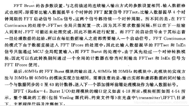
fft_burst:
module fft_Burst(bitInR,bitInI,inEn,FFT_set,Gclk,rst_n,dv,
              bitOutR,bitOutI,outEn);

input [7:0] bitInR;
input [7:0] bitInI;
input inEn;
input FFT_set;
input Gclk;
input rst_n;
output [7:0] bitOutR;
output [7:0] bitOutI;
output outEn;
output dv;

//////////////////////////////////////////////////////////////////////////////////////////////////////
reg [15:0] cnt=0;

reg s_axis_config_tvalid;
reg s_axis_data_tvalid;
reg s_axis_data_tlast;
wire m_axis_data_tvalid;
wire s_axis_data_tready;
//wire m_axis_data_tuser;
reg ctrl_we;


//////////////////////////////////////////////////////////////////////////////////////////////////////
reg start;                        //start ip core, enable for 1 cycle high. 4 cycles before input data


reg [15:0] xn_re;					    //input real part register for ip core
reg [15:0] xn_im;					    //input image part register for ip core
reg [7:0] bitOutR;					 //output real part register
reg [7:0] bitOutI;					 //output image part register
reg outEn;						       //synchronize with output, as handshake with next module

reg  [5:0] xn_index;				    //index of input for ip core


wire clr;
/////////////////////////////////////////////////////////////////////////////////////////////////////////////////////
assign clr=rst_n;                //reset of ip core, enable under high level

/***************************************************************************/

////////////////////////////////////IP时序//////////////////////////////////////
always @(posedge Gclk)
   begin
       if(clr)
           begin
               cnt <= cnt + 1'b1;
               if(start)
                   begin
                       s_axis_data_tvalid  <=1;
                       cnt <= 0;
                   end
                else if(cnt == 16'd62)
                   begin
                      s_axis_data_tlast <= 1'b1;
                   end
                else if(cnt == 16'd63)
                   begin
                      s_axis_data_tvalid <= 1'b0;
                      s_axis_data_tlast <= 1'b0;
                    end
           end
   end
/******************** Set and control FFT  *********************************/

always @ (negedge rst_n or posedge Gclk)
if (!rst_n)                                 //Initialize IP core
  begin
      start<=1'b0;

      ctrl_we<=1'b0;

      s_axis_config_tvalid<=1'b0;
      s_axis_data_tvalid <= 0;
      s_axis_data_tlast <= 0;
      xn_re<=16'h0000;
      xn_im<=16'h0000;
  end

else
  begin
  if (FFT_set)                    //if FFT_set is high, enable all write control signals
    begin
        ctrl_we<=1'b1;
        s_axis_config_tvalid <=1'b1;
    end


  if (inEn)                       //if inEn is high, enable start and disable all write control signals
    begin

        start<=1'b1;
        ctrl_we<=1'b0;
        s_axis_config_tvalid <=1'b0;
    end
    else
        start<=1'b0;


  if (s_axis_data_tvalid)							    //If new data is high, input data.
    begin
//        xn_re[10:3]<=bitInR;             //The input of IP core is 16 bit. notice the high bits which indicate sign of data
//        xn_re[11]<=bitInR[7];
//        xn_re[12]<=bitInR[7];
//        xn_re[13]<=bitInR[7];
//        xn_re[14]<=bitInR[7];
//        xn_re[15]<=bitInR[7];
//        xn_im[10:3]<=bitInI;			//we enlarge the input data by 8 times
//        xn_im[11]<=bitInI[7];
//        xn_im[12]<=bitInI[7];
//        xn_im[13]<=bitInI[7];
//        xn_im[14]<=bitInI[7];
//        xn_im[15]<=bitInI[7];
        xn_re[7:0]<=bitInR;             //The input of IP core is 16 bit. notice the high bits which indicate sign of data
        xn_re[8]<=bitInR[7];
        xn_re[9]<=bitInR[7];
        xn_re[10]<=bitInR[7];
        xn_re[11]<=bitInR[7];
        xn_re[12]<=bitInR[7];
        xn_re[13]<=bitInR[7];
        xn_re[14]<=bitInR[7];
        xn_re[15]<=bitInR[7];
        xn_im[7:0]<=bitInI;			//we enlarge the input data by 8 times
        xn_im[8]<=bitInI[7];
        xn_im[9]<=bitInI[7];
        xn_im[10]<=bitInI[7];
        xn_im[11]<=bitInI[7];
        xn_im[12]<=bitInI[7];
        xn_im[13]<=bitInI[7];
        xn_im[14]<=bitInI[7];
        xn_im[15]<=bitInI[7];
    end

  else
    begin
    xn_re<=16'h0000;
    xn_im<=16'h0000;
    end

  end


/********************************************************************/
/********************  FFT ip core  *********************************/
wire [15:0] xk_re;
wire [15:0] xk_im;

 always @(negedge rst_n or posedge Gclk)
           begin
               if(rst_n)
                   begin
                       if(s_axis_data_tvalid)
                           xn_index <= xn_index +1;
                   end
           end
/***************************************************************************/
/********************      IFFT output     *********************************/
always @ (negedge rst_n or posedge Gclk)
if (!rst_n)
  begin
      outEn<=1'b0;
  end

else
  begin
  if (m_axis_data_tvalid)                         //If dv is enable, output data's lowest 8 bits.
    begin
        outEn<=1'b1;
    end
  else
    begin
        outEn<=1'b0;
    end

  end

always @ (negedge rst_n or posedge Gclk)
if (!rst_n)
  begin
      bitOutR<=16'h00;
      bitOutI<=16'h00;
  end

else
  begin
  if (outEn)                         //If dv is enable, output data's lowest 8 bits.
    begin
        bitOutR <= xk_re[7:0];
        bitOutI <= xk_im[7:0];
    end
  else
    begin
        bitOutR<=8'h00;
        bitOutI<=8'h00;
    end

  end
fft_text fft_text_inst(
        .aclk(Gclk),
        .aresetn(clr),
        .ctrl_we(ctrl_we),
        .xn_im(xn_im),
        .xn_re(xn_re),
        .s_axis_data_tvalid(s_axis_data_tvalid),
        .s_axis_data_tlast(s_axis_data_tlast),
        .s_axis_config_tvalid(s_axis_config_tvalid),
        .s_axis_data_tready(s_axis_data_tready),
        .xk_im(xk_im),
        .xk_re(xk_re),
        .m_axis_data_tvalid(m_axis_data_tvalid)
    );
endmodule
fft_text:
`timescale 1ns / 1ps
//////////////////////////////////////////////////////////////////////////////////
// Company:
// Engineer:
//
// Create Date: 2018/12/10 17:16:18
// Design Name:
// Module Name: xfft_64text
// Project Name:
// Target Devices:
// Tool Versions:
// Description:
//
// Dependencies:
//
// Revision:
// Revision 0.01 - File Created
// Additional Comments:
//
//////////////////////////////////////////////////////////////////////////////////


module fft_text(
        input  aclk,
        input  aresetn,
        input [15:0] xn_im,
        input [15:0] xn_re,
        input s_axis_data_tvalid,
        input s_axis_data_tlast,
        input s_axis_config_tvalid,
        input ctrl_we,

//        output reg [15:0] xn_index,
        output s_axis_data_tready,
        output  [15:0]   xk_im,
        output  [15:0]   xk_re,
//        output [15:0] m_axis_data_tuser,
        output m_axis_data_tvalid
    );

        reg [7:0] s_axis_config_tdata;
        wire [31:0] m_axis_data_tdata;

        wire  [15:0] m_axis_data_tuser;
        wire    m_axis_data_tlast;
        wire    s_axis_config_tready;
        wire    event_frame_started;
        wire    event_tlast_unexpected;
        wire    event_tlast_missing;
        wire    event_status_channel_halt;
        wire    event_data_in_channel_halt;
        wire    event_data_out_channel_halt;

        wire [31:0] s_axis_data_tdata = {xn_im,xn_re};
        assign  {xk_im,xk_re} = m_axis_data_tdata;

       always @(posedge aclk or negedge aresetn)
                   begin
                       if(!aresetn)
                           begin
                               s_axis_config_tdata <= 8'b0;
                           end
                       else
                        begin
                             if(ctrl_we)
                               s_axis_config_tdata <= 8'b1011100;
                        end
                   end


        xfft_64 usr_FFT(

                .aclk(aclk),
                .aresetn(aresetn),

                .s_axis_config_tdata(s_axis_config_tdata),
                .s_axis_config_tvalid(s_axis_config_tvalid),
                .s_axis_config_tready(s_axis_config_tready),

                .s_axis_data_tdata(s_axis_data_tdata),
                .s_axis_data_tvalid(s_axis_data_tvalid),
                .s_axis_data_tready(s_axis_data_tready),
                .s_axis_data_tlast(s_axis_data_tlast),

                .m_axis_data_tdata(m_axis_data_tdata),
                .m_axis_data_tuser(m_axis_data_tuser),
                .m_axis_data_tvalid(m_axis_data_tvalid),
                .m_axis_data_tready(1'b1),
                .m_axis_data_tlast(m_axis_data_tlast),

                .event_frame_started(event_frame_started),
                .event_tlast_unexpected(event_tlast_unexpected),
                .event_tlast_missing(event_tlast_missing),
                .event_status_channel_halt(event_status_channel_halt),
                .event_data_in_channel_halt(event_data_in_channel_halt),
                .event_data_out_channel_halt(event_data_out_channel_halt)
        );


endmodule
change20:
//clk60M写clk20M读
module channge20(clk20M,clk60M,reset,inEn,outEn,dataInR,dataInI,dataOutR,dataOutI,bitIndexOut);
input clk20M;
input clk60M;
input reset;
input inEn;
input [7:0]dataInR;
input [7:0]dataInI;
output outEn;
output [7:0]dataOutR;
output [7:0]dataOutI;
output [5:0] bitIndexOut;
reg [5:0] bitIndexOut;
wire [7:0]dataOutR;
wire [7:0]dataOutI;
reg [7:0]dataInR_buf;
reg [7:0]dataInI_buf;
reg En;
wire clk60M;
always @(posedge clk60M or negedge reset)
begin
if(!reset)
begin
En<=0;
dataInR_buf<=0;
dataInI_buf<=0;
end
else begin
if(inEn)
begin
dataInR_buf<=dataInR;
dataInI_buf<=dataInI;
En<=1;
end
else begin
dataInR_buf<=0;
dataInI_buf<=0;
En<=0;
end
end
end
reg mode;
reg [7:0] k;
//clk60M64涓暟鎹啓鍏?
always @(posedge clk60M or negedge reset)
begin
if(!reset)
begin
k<=0;
end
else begin
if(En)
begin
if(k==63)
k<=0;
else
k<=k+1;
end
end
end
reg [7:0] r;
reg modetemp;
reg [1:0] cont;
always @(posedge clk60M or negedge reset)
begin
if(!reset)
begin
r<=0;
modetemp<=0;
end
else begin
if(En)
begin
if(r==63)
begin
modetemp<=1;
r<=0;
end
else
begin
r<=r+1;
modetemp<=0;
end
end
else
begin
r<=0;
modetemp<=0;
end
end
end
always @(posedge clk60M or negedge reset)
begin
if(!reset)
begin
cont<=2'b0;
mode<=0;
end
else
begin
if (cont==2'b11)
begin
mode<=0;
cont<=0;
end
else if (modetemp)
begin
mode<=1;
cont<=cont+1;
end
else
begin
if(mode)
cont<=cont+1;
else
cont<=0;
end
end
end
reg [7:0] t;
reg outEn;
reg flag;
//clk20M 64涓暟鎹鍙?
always @(posedge clk20M or negedge reset)
begin
if(!reset)
begin
t<=0;
outEn<=0;
flag<=0;
end
else begin
if(mode)
begin
flag<=1;
end
if(flag)
begin
outEn<=1;
if(t==63)
begin
t<=0;
flag<=0;
end
else t<=t+1;
end
else outEn<=0;
end
end
always @(posedge clk20M or negedge reset)
begin
if(!reset)
bitIndexOut<=0;
else
bitIndexOut<=t;
end
wire dpo;
data_rom dataromr ( //BRAM for real part: input 60MHz, output 20MHz, depth 64 bytes
.a(k),
.dpra(t),
.clk(clk60M),
.qdpo_clk(clk20M),
.d(dataInR_buf),
.qdpo(dataOutR),
.qdpo_ce(flag),
.we(En),
.dpo(dpo));
data_rom dataromi ( //BRAM for image part: input 60MHz, output 20MHz, depth 64 bytes
.a(k),
.dpra(t),
.clk(clk60M),
.qdpo_clk(clk20M),
.d(dataInI_buf),
.qdpo(dataOutI),
.qdpo_ce(flag),
.we(En),
.dpo(dpo));
endmodule
matlab仿真验证程序:
clear;
file_name='C:/Users/lyw/Desktop/fsave.txt';
fid = fopen(file_name,'r');
c = fscanf(fid,'%d');
fclose(fid);
%有符号数
for i=1: length(c)
if(c(i)>200)
b(i) = c(i)-256;
else b(i) = c(i);
end
end
d1=b(1:2:end);
d2=b(2:2:end);
comp1=d1(1:64) + j*d2(1:64);
comp2=d1(65:128) + j*d2(65:128);
%comp2=comp2/3;
c1avr=sum(comp1)/length(comp1);
c1=comp1-c1avr;
% c1=comp1;
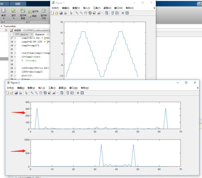
c1fft=abs(ifft(c1,64));
c2fft=abs(comp2);
plot(c1);
figure
subplot(2,1,1);
plot(c1fft);
subplot(2,1,2);
plot(c2fft);
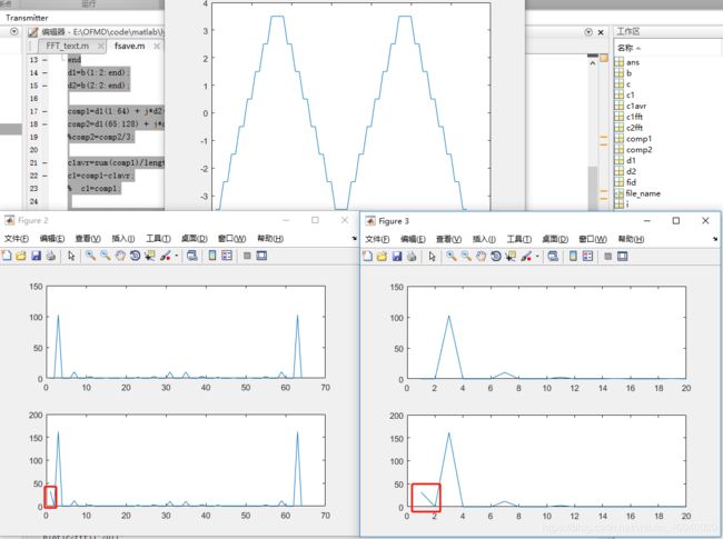
figure
subplot(2,1,1);
plot(c1fft(1:20));
subplot(2,1,2);
plot(c2fft(1:20));
tb:
`timescale 1ns/1ns
module IFFT_tb();
  reg clk20M;
  reg clk60M;
  reg rst_n;
  reg inEn;
  reg [7:0] dat_c;
  wire [7:0]dataInR;
  wire [7:0]dataInI;
  wire outEn;
  wire [7:0]dataOutR;
  wire [7:0]dataOutI;
  wire [5:0] bitIndex;

  IFFT IFFT_inst(
  .clk20M(clk20M),
  .clk60M(clk60M),
  .rst_n(rst_n),
  .inEn(inEn),
  .dataInR(dataInR),
  .dataInI(dataInI),
  .outEn(outEn),
  .dataOutR(dataOutR),
  .dataOutI(dataOutI),
  .bitIndex(bitIndex));
integer i=0;
integer j=0;

integer handle1;
    initial
        begin//sequence block

          handle1 =$fopen("C:/Users/lyw/Desktop/fsave.txt");
          #200000  $fclose(handle1);
          $stop;
        end

initial begin
    clk20M=0;
    clk60M=0;
    rst_n=0;
    inEn=0;
    dat_c = 8'b0;
//    dataInR=8'b00000000;
//    dataInI=8'b00000000;
    #200
    rst_n=1;
    inEn=1;

                    for (i=0;i<64;i=i+1)
                        begin
                          #60
                          dat_c <=(dat_c + 4'b1000);
                        end

    inEn=0;
end


 always @(posedge clk20M)
   begin
       if(inEn)
           $fwrite(handle1,"%d %d \n",dataInR,dataInI);
       else if(outEn)
           $fwrite(handle1,"%d %d \n",dataOutR,dataOutI);
   end
  assign dataInR ={13'b0,{dat_c[7]? ~dat_c[7:4] : dat_c[7:4]}};
  assign dataInI =0;
always #30 clk20M = ~clk20M;
always #10  clk60M = ~clk60M;
endmodule
在验证过程中出现的问题:
问题1、设置IP疏忽,未顺序输出;
除了幅度不同,还有感觉是在x方向上缩小了;寻找原因中。。。。。在后续的学习过程中,发现设置IP的时候没有选择顺序输出;

output [7 : 0] m_axis_data_tuser,设置为自动scaling时,该端口表示该次转换的截位(压缩倍数);如果scaling不是自动,那么不会有该信号;该信号在一帧数据的整个时间段内都有效;
问题二:采样时钟问题,部分数据丢失;


笔者发现,单独IP采样周期为20ns,而工程的IP为16ns,可能采样时间太短,造成了数据的丢失,把工程IP的数据改为20ns一周期,发现数据的波形基本一致,幅度上会有差异,下面致力于解决幅值上的差异和第一个转换数据的不准确性;
问题3:添加outEn,晚m_axis_data_tvalid一个时钟周期有效;
对整个工程进行测试:
发现处理第一个数,所有都正确;此时没有考虑扩大三倍; 幅值fpga大了1.5倍;

等到后面考虑到ADC转换精度的时候在考虑放大倍数的问题;程序控制如下:

此时考虑到三级蝶形运算的放大倍数,设置 s_axis_config_tdata <= 8'b1011100; scale=101110;进行逆运算;
还是要解决第一个数据不对的问题呀。。。。

后面对输出数据延迟一个时钟周期,fpga输出数据与matlab仿真数据完全吻合,幅度扩大了100倍;基本正确!
总结:fpga IFFT变换输出数据比实际变换后的数据扩大了100倍;(后面根据ADC转换精度决定)输入到IP的数据未经过放大,scale=101110;