用GCC开发STM32入门二
之前从网上下载了一份用GCC开发stm32的程序,也是用的stm32的库函数编程,启动文件是startup_stm32f10x_hd.s,链接脚本文件是从gcc_ride7中拷贝出的stm32f10x_flash_extsram.ld,做了些简单修改。但是编译了一下,出现了一大堆的错误。于是干脆不用这些文件,从网上查资料,自己写启动文件和链接脚本。仔细看了下startup_stm32f10x_hd.s,这个文件,发现也很简单,无非是定义了一些中断向量表和完成数据段的搬移和.bss段的清零等工作,并把程序跳转到main()函数。然后链接脚本文件告知链接器,把所有目标文件相应的段连接到一起,并把目标文件中的“变量地址”“函数地址”重定位至正确的地址空间; 编写前需要知道C程序编译后的典型内存布局 ,单片机的启动流程以及链接脚本文件的作用和编写等知识。部分知识,摘自网络。
《Cortex-M3权威指南》一书中有如下开发流程图:
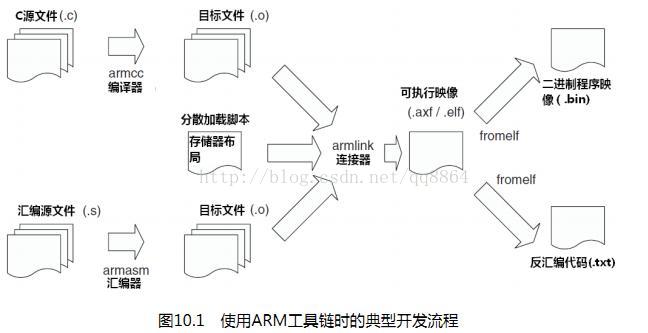
由图可知,用C语言进行stm32的程序开发,仍然是:写代码--->编译、连接--->下载到flash这样一个过程。只不过除此以外,比较重要的还需要 知道这样几点:
1、如何访问此种单片机的外围设备寄存器;
2、如何书写此种单片机的中断服务程序;
3、此种单片机复位后,从什么地址处开始执行代码;然后我们如何告诉编译工具把代码按照这个入口地址开始安排我们的代码。
4、需不需要为构建C语言的运行环境作一些工作,也就是启动代码。
5、通过命令行选项通知编译器为特定的单片机生成代码。
一、下载GNU工具链,搭建环境
二、熟悉整体的开发流程
三、编写一个最精简的代码1、一个main函数就足够了吗?
先让我们简单回顾一下在PC机,一个程序的执行过程大概是怎样的。因为程序是在操作系统的管理下运行的,过程大概为:
操作系统----------> 启动代码(编译器自动加入,做一些堆栈、全局变量的初始化工作)-----------> main
然而在裸奔的单片机上,操作系统没有了,所以原来由操作系统和编译器作的事情,现在需要我们手工DIY了(如果交叉编译工具没有为我们做好这些事 情的话,因为我也不知道gcc现在有没有为stm32做好这一切,所以我暂时假定什么都得靠自己)。
2、C程序的典型内存布局
+-------------------------------+
| |
| 堆栈 |
| |
+ - - - - - - - - - - - - - - - +
| |
| |
| |
| |
| |
| |
| |
| |
| |
+ - - - - - - - - - - - - - - - +
| |
| 堆 |
| |
+-------------------------------+
| |
| 未初始化的数据 |
| .bss段 |
| |
+-------------------------------+
| |
| 初始化的数据 |
| .data段 |
| |
+-------------------------------+
| |
| 正文 |
| .text段 |
| .rodata段 |
| |
+-------------------------------+
上图中,正文对应的是可执行代码.text和常量表格数据等.rodata,.data对应初始化了的全局变量,编译后将位于可执行文件中,由启动代码负责加载 到数据区中(在单片机中这部分数据会存于flash中,需要有启动代码把这部分内容拷贝到sram中),.bss段是没有初始值的全局变量,由启动代码把这 部分内容全初始化为0;为了保证C程序的执行,还需要设置好程序运行时的堆栈区。
在有了这些基础知识后,除了main以外,我们还需要做些什么就比较清楚了:设置堆栈区,把编译好的内容放到单片机中正确的地方中去。
3、设置堆栈区和启动代码
Cortex-m3内核在地址0x0000 0000处存放一个向量表,向量表的第0个单元,也即地址0x0000 0000处存放的是堆栈顶的地址,Cortex-m3复位后即从该处 取出数据用以初始化MSP寄存器。向量表中的内容是32位的地址,这些地址是中断异常服务程序的入口地址,其中向量表的第一个单元,
即地址0x0000 0004处存放的是复位向量,也就是说Cortex-m3复位后,执行该向量(可理解为函数指针)指向的复位代码。看看代码吧:
__attribute__ ((section(".stackarea")))
static unsigned long pulStack[STACK_SIZE];
这一句定义了一个pulStack的数组,程序把这个数组作为了堆栈区。这条语句使用了__attribute__ ((section(".stackarea"))) 把数组定位在
了.stackarea这个段中。
typedef void (* pfnISR)(void);
__attribute__ ((section(".isr_vector")))
pfnISR VectorTable[] =
{
(pfnISR)((unsigned long)pulStack + sizeof(pulStack)), // The initial stack pointer
ResetISR, // The reset handler
NMIException,
HardFaultException
};
定义了一个数组VectorTable,作为向量表,定位于.isr_vector段中。通过链接脚本的控制这个表将放在正文区的最开始,正文区又将从flash的最开始 存放,这样这个向量表就会起到相当于存放在0x0000 0000开始的地址空间的效果。
向量表的第0个单元是((unsigned long)pulStack + sizeof(pulStack)),这是数组的最后一个元素,因为Cortex-m3的堆栈是向下增长的。
向量表的第1个单元是ResetISR,它指向复位处理的代码,也是整个程序的入口。本程序用它来实现启动代码的功能。
extern unsigned long _etext;
extern unsigned long _data;
extern unsigned long _edata;
extern unsigned long _bss;
extern unsigned long _ebss;
void ResetISR(void)
{
unsigned long *pulSrc, *pulDest;
//
// Copy the data segment initializers from flash to SRAM.
//
pulSrc = &_etext;
for(pulDest = &_data; pulDest < &_edata; )
{
*pulDest++ = *pulSrc++;
}
//
// Zero fill the bss segment.
//
for(pulDest = &_bss; pulDest < &_ebss; )
{
*pulDest++ = 0;
}
//
// Call the application's entry point.
//
main();
}
这段代码用到了通过连接器赋值的几个变量值。_etext的值为正文段结尾处的地址,这之后的flash空间是初始化的数据值,应该复制到sram中去,
_data、_edata的值分别为数据段的开始和结尾处的地址,这部分应该是sram的地址。
pulSrc = &_etext;
for(pulDest = &_data; pulDest < &_edata; )
{
*pulDest++ = *pulSrc++;}
这部分代码就是将保存于flash中的初始化数据复制到sram中。
上面代码中的第二个循环是将.bss段清零。最后调用main进入到我们的主程序。
4、访问外围设备寄存器
Cortex-m3的外围设备寄存器位于线性的4GB地址空间中,所以定义指向该外围设备所处地址的指针即可访问了。
#define GPIOC_CRL (*((volatile unsigned int*)(0x40011000)))
#define GPIOC_BSRR (*((volatile unsigned int*)(0x40011010)))
#define GPIOC_BRR (*((volatile unsigned int*)(0x40011014)))
#define RCC_APB2ENR (*((volatile unsigned int*)(0x40021018)))
使用宏GPIOC_CRL等即可访问相应的寄存器。
5、链接
gcc编译C源程序文件后,得到目标文件,目标文件需要连接得到最后的可执行文件,程序才能执行。一般来说,目标文件包含
.text段: 可执行代码
.rodata段: 只读的数据,对应程序中的常量
.data段: 初始化的全局变量
.bss段: 未初始化的全局变量
连接器所作的工作简单的讲就是,把所有目标文件相应的段连接到一起,并把目标文件中的“变量地址”“函数地址”重定位至正确的地址空间;
比如,对于stm32来说向量表,.text和.rodata就应该放到从0x0800 0000开始的flash,.data,.bss和堆栈就应该定位至从0x2000 0000开始的sram中。 这些定位都可以通过链接脚本进行控制。
MEMORY
{
FLASH (rx) : ORIGIN = 0x08000000, LENGTH = 0x20000
SRAM (rwx) : ORIGIN = 0x20000000, LENGTH = 0x5000
}
这些语句说明了flash和sram开始的地址以及大小。
.text :
{
KEEP(*(.isr_vector .isr_vector.*))
*(.text .text.*)
*(.rodata .rodata*)
_etext = .;
} > FLASH
按.isr_vector, .text, .rodata的顺序排列正文段的内容;回忆前述VectorTable[]数组就被定为与.isr_vector段中,所以这段脚本就保证了向量表为 与正文区的最开端,将存放于0x0800 0000开始的位置了。但向量表不是应该从0x0000 0000开始吗?原来stm32可以通过boot0、boot1引脚的配置将 flash映射到0x0000 0000处。具体可参考stm32的数据手册。 _etext = .; 这条语句把计数器“.”的值赋给了变量_etext;“.”现在的值就为.text的尾部。 另,后面的.data、.bss、.stackarea部分可自行分析,原理一样。
四、编译程序
step1: arm-elf-gcc -mcpu=cortex-m3 -mthumb gpio_test.c -nostartfiles -T stm32f103VBT6.ld -o gpio_test.o
注意参数 -nostartfiles指示不要包含编译器自带的启动代码,-T stm32f103VBT6.ld表示使用stm32f103VBT6.ld这个链接脚本。
step2: arm-elf-ld -T stm32f103VBT6.ld -o gpio_test.out gpio_test.o
同样使用stm32f103VBT6.ld这个链接脚本。
step3: arm-elf-objcopy -Obinary gpio_test.out gpio_test.bin
从elf的文件格式中得到最终需要的gpio_test.bin二进制目标文件。
step4: 使用官方的flash下载demo程序将得到的gpio_test.bin通过usart1烧录至芯片。
五、下载程序和仿真调试
如果只是下载程序,可以通过串口,用官方提供的下载工具下载。
如果有jlink仿真器,可以用jiinkARM工具下载,这个工具在安装jlink驱动的时候已经安装了。
调试和仿真,linux下可以用openocd和openjtag,或者用GDB加jlink的GDBserver,windows下可以用GDBserver和可视化的GDB调试器insight。
以下是一个简单的流水灯示例和makefile,库使用的是3.5的官方库
/*************************************************/
/* filename: stm32f103VET6.ld */
/* linkscript for STM32F103VET6 microcontroller */
/* */
/*************************************************/
MEMORY
{
FLASH (rx) : ORIGIN = 0x08000000, LENGTH = 0x80000
SRAM (rwx) : ORIGIN = 0x20000000, LENGTH = 0x10000
}
/* Section Definitions */
SECTIONS
{
.isr_vector :
{
KEEP(*(.isr_vector))
isr.o(.text)
. = ALIGN(4);
_eisr_vector = .;
}
.text : AT (_eisr_vector)
{
_text = .;
*(EXCLUDE_FILE(isr.o) .text)
*(.rodata)
. = ALIGN(4);
_etext = .;
} > SRAM
.data :
{
_data = .;
*(.data)
. = ALIGN(4);
_edata = . ;
} > SRAM
/* .bss section which is used for uninitialized data */
.bss (NOLOAD) :
{
_bss = . ;
*(.bss)
. = ALIGN(4);
_ebss = . ;
} > SRAM
_end = . ;
}
//isr.c文件,省略号代表没写全,可以找.s启动文件中把它补全
extern int main(void);
void ResetISR(void);
void NMIException(void);
void HardFaultException(void);
...
typedef void (*pfnISR)(void); // Pointer to exception handle function
__attribute__ ((section(".isr_vector")))
pfnISR VectorTable[] =
{
(pfnISR)(0x20010000), // The initial stack pointer is the top of SRAM
ResetISR, // The reset handler
NMIException,
HardFaultException,
...
};
//*****************************************************************************
//
// The following are constructs created by the linker, indicating where the
// the "data" and "bss" segments reside in memory. The initializers for the
// for the "data" segment resides immediately following the "text" segment.
//
//*****************************************************************************
extern unsigned long _eisr_vector;
extern unsigned long _text;
extern unsigned long _etext;
extern unsigned long _data;
extern unsigned long _edata;
extern unsigned long _bss;
extern unsigned long _ebss;
void ResetISR(void)
{
unsigned long *src, *dst;
// copy the text segment from flash to SRAM
src = &_eisr_vector;
dst = &_text;
while (dst < &_etext) {
*dst++ = *src++;
}
// Copy the data segment initializers from flash to SRAM.
dst = &_data;
while (dst < &_edata) {
*dst++ = *src++;
}
// Zero fill the bss segment.
for(dst = &_bss; dst < &_ebss; dst++) {
*dst = 0;
}
// Call the application's entry point.
main();
}
//main.c文件
#include "stm32f10x.h"
GPIO_InitTypeDef GPIO_InitStructure;
void RCC_Configuration(void);
void Delay(__IO uint32_t nCount);
int main(void)
{
//uint16_t a;
/* System Clocks Configuration **********************************************/
RCC_Configuration();
//
/* Configure all unused GPIO port pins in Analog Input mode (floating input
trigger OFF), this will reduce the power consumption and increase the device
immunity against EMI/EMC *************************************************/
RCC_APB2PeriphClockCmd( RCC_APB2Periph_USART1 |RCC_APB2Periph_GPIOA | RCC_APB2Periph_GPIOB |
RCC_APB2Periph_GPIOC | RCC_APB2Periph_GPIOD |
RCC_APB2Periph_GPIOE, ENABLE);
GPIO_InitStructure.GPIO_Pin = GPIO_Pin_6|GPIO_Pin_7; //D1 D2
GPIO_InitStructure.GPIO_Mode = GPIO_Mode_Out_PP;
GPIO_InitStructure.GPIO_Speed = GPIO_Speed_50MHz;
GPIO_Init(GPIOC, &GPIO_InitStructure);
GPIO_InitStructure.GPIO_Pin = GPIO_Pin_6|GPIO_Pin_13;//D3, D4
GPIO_Init(GPIOD, &GPIO_InitStructure);
while (1)
{
GPIO_SetBits(GPIOC, GPIO_Pin_6);// D1亮
Delay(0xAFFFF);
GPIO_SetBits(GPIOC, GPIO_Pin_7 ); //D2亮
GPIO_ResetBits(GPIOC, GPIO_Pin_6); //D1灭
Delay(0xAFFFF);
GPIO_SetBits(GPIOD, GPIO_Pin_13 ); //D3亮
GPIO_ResetBits(GPIOC, GPIO_Pin_7); //D2灭
Delay(0xAFFFF);
GPIO_SetBits(GPIOD, GPIO_Pin_6 ); //D4亮
GPIO_ResetBits(GPIOD, GPIO_Pin_13); //D3灭
Delay(0xAFFFF);
GPIO_ResetBits(GPIOD, GPIO_Pin_6); //D4灭
}
}
void RCC_Configuration(void)
{
/* Setup the microcontroller system. Initialize the Embedded Flash Interface,
initialize the PLL and update the SystemFrequency variable. */
SystemInit();
}
void Delay(__IO uint32_t nCount)
{
for(; nCount != 0; nCount--);
}
//编译本工程的makefile文件
BINARY = main
PREFIX = arm-elf
CC = $(PREFIX)-gcc
LD = $(PREFIX)-ld
OBJCOPY = $(PREFIX)-objcopy
OBJDUMP = $(PREFIX)-objdump
CFLAGS= -O2 -mcpu=cortex-m3 -mthumb -nostartfiles -I inc/
LDSCRIPT =stm32f103VET6.ld
LDFLAGS = -T $(LDSCRIPT)
OBJS = stm32f10x_gpio.o stm32f10x_rcc.o isr.o
OBJS += $(BINARY).o
OBJS += core_cm3.o
OBJS += system_stm32f10x.o
.PHONY: clean
all:images
images: $(BINARY).hex $(BINARY).bin $(BINARY).elf $(BINARY).list
$(OBJS):%.o:%.c
$(CC) -c $(CFLAGS) $< -o $@
%.elf: $(OBJS) $(LDSCRIPT)
$(LD) -o $(*).elf $(OBJS) $(LDFLAGS)
%.bin: %.elf
$(OBJCOPY) -Obinary $(*).elf $(*).bin
%.hex:%.elf
$(OBJCOPY) -Oihex $(*).elf $(*).hex
%.list: %.elf
$(OBJDUMP) -S $(*).elf > $(*).list
clean:
rm -f *.o
rm -f *.d
rm -f *.elf
rm -f *.bin
rm -f *.hex
rm -f *.list
完
本工程的示例代码放在了CSDN上,可以免费下载。搭建好环境后只需要make一下,就能生成.hex和.bin文件。注意开启-O2优化,生成的代码和keilMDK比了比,差不多大。但不开启-O2优化,生成代码量是keil for arm的两倍多。