LTE物理层概述及基本概念讲解
There are two types of frame structure in the LTE standard, Type 1 and Type 2. Type 1 uses Frequency Division Duplexing (uplink and downlink separated by frequency), and TDD uses Time Division Duplexing (uplink and downlink separated in time). This overview covers both LTE FDD Type 1 signals and LTE TDD Type 2 signals described in the standard documents listed in the About Opts BHD and BHE: LTE Modulation Analysis topic.
This overview is not an exhaustive description of the physical layer, but is intended to provide you with a useful background when you configure the 89600 VSA LTE demodulator to make measurements.
For a more in depth explanation of LTE, see the 3GPP Long Term Evolution: System Overview, Product Development, and Test Challenges application note. Keysight has also released a book called LTE and the Evolution to 4G Wireless: Design and Measurement Challenges which contains detailed information on many of the aspects of LTE.
Terminology
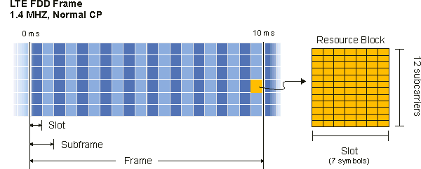
First, an introduction to some of the terms used in describing an LTE Frame. There are six time units: frame, half-frame, subframe, slot, symbol, and the basic time unit (Ts), as shown in the following table.
| Time Unit |
Value |
|---|---|
| Frame | 10 ms |
| Half-frame | 5 ms |
| Subframe | 1 ms |
| Slot | 0.5 ms |
| Symbol | (0.5 ms) / 7 for normal CP (0.5 ms) / 6 for extended CP |
| Ts | 1/(15000 * 2048) sec » 32.6 ns |
Below is an illustration of an FDD frame.
A resource block (RB) is the smallest unit of resources that can be allocated to a user. The resource block is 180 kHz wide in frequency and 1 slot long in time. In frequency, resource blocks are either 12 x 15 kHz subcarriers or 24 x 7.5 kHz subcarriers wide The number of subcarriers used per resource block for most channels and signals is 12 subcarriers.
The 89600 VSA LTE demodulator currently only supports resource blocks that are 12 subcarriers wide.
Frequency units can be expressed in number of subcarriers or resource blocks. For instance, a 5 MHz downlink signal could be described as 25 resource blocks wide or 301 subcarriers wide (DC subcarrier is not included in a resource block).
The underlying data carrier for an LTE frame is the resource element (RE). The resource element, which is 1 subcarrier x 1 symbol, is the smallest discrete part of the frame and contains a single complex value representing data from a physical channel or signal.
Bandwidths
The bandwidths defined by the standard are 1.4, 3, 5, 10, 15, and 20 MHz. The table below shows how many subcarriers and resource blocks there are in each bandwidth for uplink and downlink.
| Bandwidth |
Resource Blocks |
Subcarriers (downlink) |
Subcarriers (uplink) |
|---|---|---|---|
| 1.4 MHz | 6 | 73 | 72 |
| 3 MHz | 15 | 181 | 180 |
| 5 MHz | 25 | 301 | 300 |
| 10 MHz | 50 | 601 | 600 |
| 15 MHz | 75 | 901 | 900 |
| 20 MHz | 100 | 1201 | 1200 |
For downlink signals, the DC subcarrier is not transmitted, but is counted in the number of subcarriers. For uplink, the DC subcarrier does not exist because the entire spectrum is shifted down in frequency by half the subcarrier spacing and is symmetric about DC.
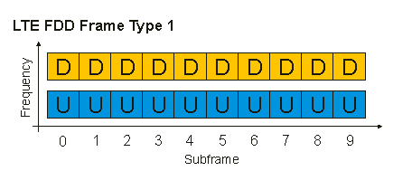
FDD frame type 1
In FDD mode, uplink and downlink frames are both 10ms long and are separated either in frequency or in time.
For full-duplex FDD, uplink and downlink frames are separated by frequency and are transmitted continuously and synchronously.
For half-duplex FDD, the only difference is that a UE cannot receive while transmitting.
The base station can specify a time offset (in PDCCH) to be applied to the uplink frame relative to the downlink frame.
TDD frame type 2
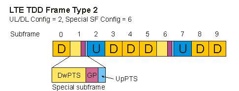
In TDD mode, the uplink and downlink subframes are transmitted on the same frequency and are multiplexed in the time domain. The locations of the uplink, downlink, and special subframes are determined by the uplink-downlink configuration. There are seven possible configurations given in the standard. The following is an illustration of a TDD frame with uplink-downlink configuration set to 2 and special subframe configuration set to 6.
Special subframes
Special subframes are used for switching from downlink to uplink and contain three sections: DwPTS, GP, and UpPTS.
DwPTS is the Downlink Pilot Time Slot. DwPTS contains P-SS. PDSCH can also be transmitted during DwPTS when DwPTS is configured to be longer than a slot.
UpPTS is the Uplink Pilot Time Slot. UpPTS can contain PRACH and SRS, but cannot contain or PUCCH or PUSCH.
GP is a guard period between DwPTS and UpPTS. PRACH format 4 begins in the guard period. Otherwise, nothing else is transmitted during the guard period.
The lengths of these three sections are determined by the special subframe configuration index (specified by the Dw/Gp/Up Len parameter). There are 9 possible configurations.
UL/DL configuration
The uplink-downlink configuration (specified by UL/DL Config) of a TDD frame determines the locations of uplink, downlink, and special subframes. There are 7 possible uplink-downlink configurations.
Subframes 0 and 5 and DwPTS in TDD frames are always allocated to downlink transmissions.
UpPTS and the subframe after a special subframe are always allocated to uplink transmissions.
Subframe 1 is always configured to be a special subframe. Subframe 6 can also be configured to be a special subframe.
Uplink
Uplink user transmissions consist of uplink user data (PUSCH), random-access requests (PRACH), user control channels (PUCCH), and sounding reference signals (SRS).
FDD and TDD uplink transmissions have the same physical channels and signals. The only difference is that TDD frames include a special subframe, part of which can be used for SRS and PRACH uplink transmissions.
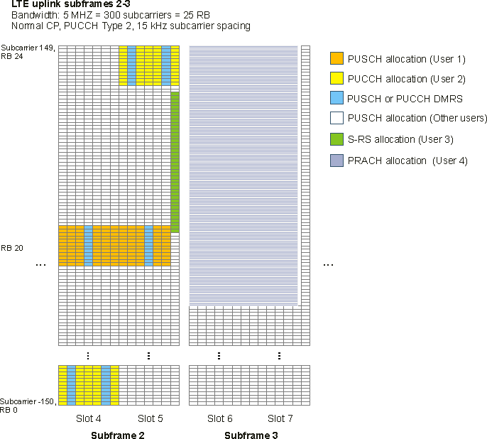
The following illustration shows part of an LTE uplink frame and contains an allocation for each type of uplink channel. The illustration is applicable to both TDD and FDD.
User 1 has a PUSCH allocation of [RB 20, slots 4-5], and User 2 has a PUCCH allocation of [subframe 2, PUCCH index 0]. User 3 has been given an SRS allocation of subcarrier 94 to 135 in subframe 2, and User 4 is transmitting in a PRACH allocation.
A user cannot transmit both PUCCH and PUSCH data in the same slot.
TDD
In TDD mode, uplink and downlink transmissions occupy the same frequency spectrum but are separated in time. Uplink users transmit during subframes configured for uplink. In addition to uplink subframes, UE's can transmit random-access requests (PRACH) and SRS during the UpPTS section of the special subframe.
FDD
The uplink FDD frame is the same length as the downlink frame and contains only uplink user transmissions.
Modulation
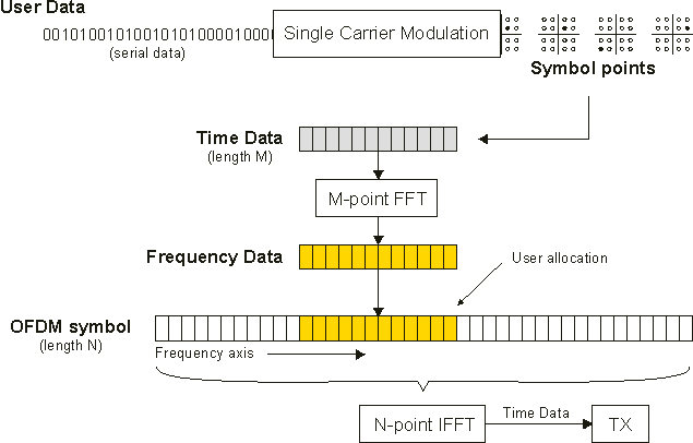
For uplink data signals (PUSCH), the LTE standard uses Single Carrier - Frequency Division Multiple Access (SC-FDMA) modulation, which has a lower peak-to-average power ratio, meaning lower cost amplifiers and less power usage.
In SC-FDMA, the user data is modulated onto a single carrier modulation format (QPSK, 16QAM, or 64QAM), and the time domain symbols are transformed to the frequency domain by an FFT. Then the frequency domain points are mapped onto the subcarriers assigned to the user in the OFDM symbol. Finally, an IFFT is performed on the entire OFDM symbol and resulting time data is transmitted. The following image illustrates this process.
The value M in the M-point FFT in the illustration above is the width (in subcarriers) of the uplink allocation assigned to the user. Typically a UE is not allocated the entire spectrum, therefore M is less than or equal to N.
For symbols that contain demodulation reference signals, PRACH, PUCCH, or SRS, the uplink transmitter places the modulation symbols directly onto the OFDM subcarriers, performs the IFFT, and transmits the data in a manner similar to downlink OFDMA.
Synchronization
Uplink signals do not have a dedicated sync signal. In a real world environment, the uplink signals would be synchronized using the downlink signal. However, to allow analysis of uplink separate from downlink when using the 89600 VSA LTE demodulator, uplink frames can be synchronized using PUCCH DM-RS, PUSCH DM-RS, PRACH, or SRS.
Reference signals
There are two types of uplink reference signals, the Demodulation Reference Signal (DMRS) and the Sounding Reference Signal (SRS). Reference signals are used for channel estimation or equalization.
DMRS
The Demodulation Reference Signal (DMRS) is used by the base station to equalize and demodulate the UE's transmissions.
The PUSCH demodulation reference signal is a Zadoff-Chu sequence, which results in constellation points on a circle centered about the origin.
The PUCCH demodulation reference signal, however, is a reference sequence transmitted on a rotated QPSK constellation. The amount of rotation is determined by cyclic shift (a) as defined in the standard.
Each uplink user transmits a Demodulation Reference Signal during certain symbols in each resource block allocated to the user. DMRS is transmitted on all subcarriers allocated to the user during the symbols listed in Table 5.5.2.2.2-1 in 3GPP TS 36.211.
SRS
The sounding reference signal (SRS) is transmitted separately from PUCCH and PUSCH. SRS can be transmitted on any number of subcarriers in the last symbol in an uplink subframe whether or not the subcarriers are assigned to another channel. The exception is that PRACH transmissions and PUCCH Format 1 and 2/2a/2b transmissions take precedence over SRS transmissions.
SRS is transmitted by a UE to give the base station an idea of the channel characteristics for that UE. The base station can use the information to assign good uplink allocations for the UE to transmit on.
Physical channels
PUCCH
There is only one control channel transmitted by uplink users—the Primary Uplink Control Channel (PUCCH)—which contains information including channel quality info, acknowledgements, and scheduling requests.
PUCCH is assigned by subframe instead of by slot. The location of PUCCH in the first slot alternates in the pattern:
Resource block 0, N-1, 1, N-2, 2, N-3, ...
where N is the frequency width of the frame in units of RB.
The location of the PUCCH resource block in the second slot is the one that mirrors the location of the resource block in the first slot. For example, in a 5 MHz uplink LTE signal, a PUCCH allocation of (subframe 1, PUCCH index 0) means that PUCCH is transmitted on (Slot 2, RB0) and (Slot 3, RB24).
The PUCCH index (set by the First RB parameter) determines which resource block in the first and second slots of the subframe is used for PUCCH.
PUCCH's modulation format is determined by PUCCH type and can be QPSK, BPSK, On/off keying, or a combination of QPSK and BPSK. See the PUCCH topic for a table of PUCCH types and their corresponding modulation formats.
PUSCH
The Primary Uplink Shared Channel (PUSCH) is used by uplink users to transmit data to the base station. All subcarriers not allocated for PRACH, PUCCH, or SRS are available for assignment to users. PUSCH data is modulated using SC-FDMA.
PUSCH data is transmitted using QPSK, 16QAM, or 64QAM as the single carrier modulation type before spreading (FFT, subcarrier mapping, then IFFT).
PRACH
The Physical Random Access Channel (PRACH) is used by a uplink user to initiate contact with a base station. The base station broadcasts some basic cell information, including where random-access requests can be transmitted. A UE then makes a PRACH transmission asking for PUSCH allocations, and the base station uses the downlink control channel (PDCCH) to reply where the UE can transmit PUSCH.
PRACH consists of a cyclic prefix followed by the PRACH sequence. There are five PRACH preamble formats with various CP length and sequence lengths. Format 4 is short enough to be transmitted during the GP and UpPTS sections of the special subframe and is only applicable to the TDD frame type. PRACH preamble formats are listed in Table 5.7.1-1 in 3GPP Technical Specification 36.211.
In the frequency domain, PRACH spans 6 resource blocks of spectrum. PRACH formats 0, 1, 2, and 3 have a tighter subcarrier spacing of 1.25 kHz. This means that the OFDM symbol duration is 800 ms. PRACH format 4 has a subcarrier spacing of 7.5 kHz and a symbol duration of ~133 ms.
The frequency location of PRACH is determined by upper layer parameters.
Downlink
The downlink frame contains the information being sent to the users that are currently connected to the base station. The frame also contains physical signals for synchronization (P-SS, S-SS), channel compensation (C-RS), and control channels for managing user allocations and other tasks.
Multiple antenna ports - Spatial Multiplexing and Transmit Diversity
The LTE downlink frame can be configured to use multiple antenna ports to transmit data to the UEs. Multiple antenna ports can be used to provide greater data reliability (transmit diversity) or to increase data rate (spatial multiplexing).
Transmit diversity uses multiple C-RS antenna ports on the base station to transmit the same amount of data as one antenna port. In this case, the data is coded so that the signals from the antenna ports add together in the channel allowing the UE to equalize and demodulate the data with greater reliability. In addition, the UE only needs one antenna to demodulate the data. Transmit diversity is not technically MIMO since MIMO stands for multiple input, multiple output.
Spatial multiplexing can be used to send data to UE's that have more than one receive antenna. Spatial Multiplexing uses multiple antenna ports to increase the data transmission capacity of the frame by using space as a third dimension (in addition to time and frequency) through which to send data. Spatial Multiplexing can be done using C-RS antenna ports (0-3) or UE-RS antenna ports (ports 7-8 for Dual-Layer Beamforming). For details on antenna ports, see the Antenna Ports and Transmit-Receive Paths topic.
Modulation
Channels and signals are handled at different stages of the transmit chain. Channels contain data that originates at higher layers.
Signals, which include the reference signal and sync signals, contain known information that does not originate from higher layers. The signals are used by the receiver to perform certain Physical layer functions such as synchronization and equalization.
Signal subcarrier values are generated and mapped directly onto the OFDM subcarriers. Channel data undergoes several other steps before being mapped onto the OFDM subcarriers.
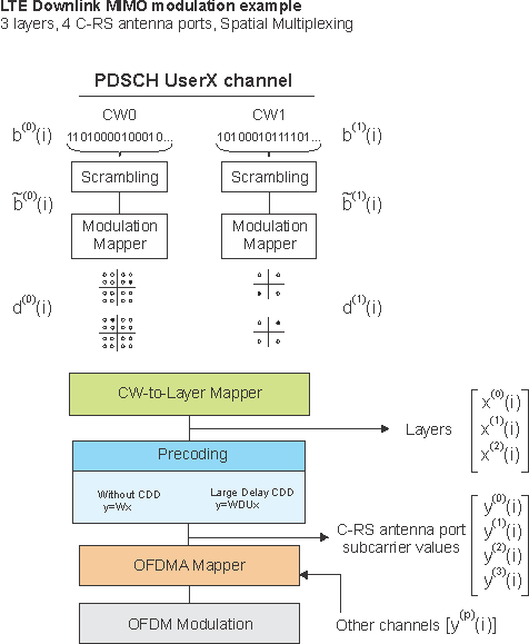
The following is an illustration of the LTE downlink transmit chain for a user's PDSCH channel. In this example, there are four C-RS antenna ports and three layers. The PDSCH channel shown below is using spatial multiplexing on the C-RS antenna ports. Other channels go through a similar process, except that they use one codeword and Transmit Diversity only.
Note that multi-layer PDSCH allocations using UE-RS beamforming do not undergo precoding.
The different sections of the illustration above are explained in the following sections.
Codewords
Codewords are simply separate streams of data that contain the information to be sent through a physical channel. There are two codewords defined for LTE: CW0 and CW1. Every channel uses CW0. PDSCH (user data) has the option of using CW1. Also, CW1 is only available when using spatial multiplexing.
The first step in the modulation process is to place data that is to be transmitted through a particular channel into the codewords for that channel.
Scrambling and modulation
Next, the data in each codeword is scrambled using a scrambling sequence for protection against burst errors. Then the binary data from this scrambling process is split into chunks depending on the modulation type chosen (6 bits for 64QAM, 4 bits for 16QAM, etc.) and mapped to complex valued modulation symbols.
Codeword to layer mapping
Once a physical channel's codewords have been scrambled and modulated, the codewords are mapped onto the layers. There can be up to as many layers as there are antenna ports.
Codeword-to-layer mapping splits the data into layers. Since codeword-to-layer mapping is basically a demultiplexing process, the total number of modulation symbols in all layers remains the same as that in the codewords.
Below is a table which lists the different codeword-layer combinations defined in the standard for PDSCH transmitted on C-RS antenna ports:
| Number of codewords |
Number of layers |
Multiplexing |
|---|---|---|
| 1 | 1 | Direct mapping (Single antenna) or Spatial Multiplexing |
| 2 | Transmit Diversity or Spatial Multiplexing | |
| 4 | Transmit Diversity | |
| 2 | 2 | Spatial Multiplexing |
| 3 | Spatial Multiplexing | |
| 4 | Spatial Multiplexing |
At this point in the transmit chain for the current physical channel, the layer data is still specific to the physical channel. There is no concept of "frame" (resource blocks, subcarriers, antenna ports, or other channels and signals). Also, each physical channel can have a different number of layers.
The LTE demodulator provides traces that show IQ or error vector data vs. subcarrier or symbol. The content of these traces comes from the selected layer. However, layers do not exist in the context of resource blocks. How can these traces show layer data in the context of resource elements and symbols?
The answer is that the demodulator undoes the precoding to recover the original modulation symbols in the layers for each physical channel and then remaps those modulation symbols back onto the physical channel allocations in the frame. The values shown on the layer traces do not have a direct physical correspondence to the subcarrier that they are mapped to. However, there is still an indirect correspondence between modulation symbols and the actual subcarriers. For instance, if you corrupt one of the subcarriers in physical channel's allocation by adding a sine wave at that particular frequency, you will see that the EVM of more than one modulation symbol on the physical channel's layer trace will be affected.
Precoding
Next, the layers are precoded using a precoding matrix defined by Section 6.3.4.2 in 3GPP TS 36.211. The result of precoding is a set of modulation symbols that are to be mapped directly onto the subcarriers. Precoding involves multiplying the layers matrix with a precoding matrix which creates the antenna port subcarrier values that are sent to the OFDMA mapper and then to the antenna ports.
For the single-antenna case, precoding is just a direct assignment of the layer contents to the antenna port data for the current physical channel.
For multiple-antennas, there are two types of precoding: transmit diversity precoding and spatial multiplexing precoding. In addition, spatial multiplexing can be either Without CDD (cyclic delay diversity) or with Large Delay CDD.
Spatial Multiplexing precoding reduces correlation between the layers. This makes it easier for the antenna port signals to be separated using MIMO techniques once they are received.
Instead of precoding, beamforming can be used. Multi-layer spatial multiplexing can also be done using UE-RS antenna ports and each layer can be beamformed differently from the others.
OFDMA Mapping
After layer data for the physical-layer channels is precoded to create C-RS antenna port data, the OFDMA mapper combines the precoded values from physical-layer channels together with the reference signal and sync signals and places the subcarrier values into the appropriate locations in an OFDM symbol.
This OFDMA symbol mapping is performed separately for each antenna port. For more information about antenna ports and their respective contents, see the Antenna Ports and Transmit-Receive Paths topic.
OFDM Modulation
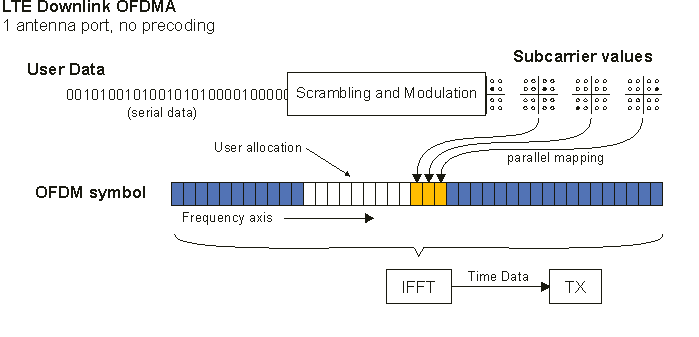
After values have been assigned for all subcarriers in an OFDM symbol for an antenna port (including the reference signal and control channels), the symbol is sent through an IFFT, which converts the symbol into time data. A cyclic prefix is appended and the time data is transmitted. The following image illustrates the entire TX chain for the single antenna case, which performs OFDM modulation directly after scrambling and modulation (no precoding). The difference when precoding is used is that the subcarrier values in the image below are replaced with the complex antenna port values that are a combination of the subcarrier values from each layer.
OFDM has a large peak-to-average power ratio which means that the amplifiers have to be higher quality and are more expensive (and are also more power hungry).
Synchronization
There are two downlink synchronization signals, the Primary Synchronization Signal (P-SS) and the Secondary Synchronization Signal (S-SS).
For FDD, P-SS is present in the last symbol, and S-SS is present in the second-to-last symbol of slots 0 and 10 in every frame.
For TDD, P-SS is present in the third symbol in slots 2 and 12 in every frame. S-SS is present in the last symbol of slots 1 and 11 in every frame.
The middle 72 subcarriers in these symbols are reserved for P-SS and S-SS, but only the center 62 subcarriers are used so that sync signals are more recognizable (easier to cross correlate).
The location of these sync signals is the same for every bandwidth, which makes locking onto a signal easier when the bandwidth is not known.
Reference signals
The downlink LTE reference signals are discussed in the following sections.
Cell specific Reference Signal (C-RS)
The Cell-specific Reference Signal (abbreviated C-RS or just RS) is transmitted on resource elements spread throughout the frame in specific locations as defined by the standard. The Cell-specific RS is used by the UE's to compensate the downlink frame for channel frequency response and cross-channel effects so that the signal can be demodulated.
Antenna ports 0-3 each have unique C-RS locations. Antenna ports do not transmit on resource elements allocated for RS on other antenna ports.
UE-specific Reference Signal (UE-RS)
In addition to the Cell-specific RS, the base station may transmit UE-specific RS in RBs allocated to the PDSCH of a UE. In LTE Release 8, UE-specific RS is used to accomplish single-layer beamforming and is transmitted on antenna port 5.
In Release 9, UE-RS for single-layer beamforming can be transmitted on antenna port 5, 7, or 8. UE-RS for dual-layer (spatial multiplexing) beamforming is transmitted on antenna ports 7 and 8. See 3GPP TS 36.211, Section 6.10.3 for more information.
The LTE demodulator only supports viewing beam patterns for linear antenna arrays. The number of elements in an antenna group and spacing between elements is specified by the Antenna Group parameters.
Positioning Reference Signal (P-RS)
The Positioning RS is used to enhance UE geolocation accuracy. The P-RS is transmitted periodically in certain frames and occupies certain resource elements within a rectangular area in the frame (RBs x SFs) as defined by the P-RS parameters.
Multicast/Broadcast Single Frequency Network Reference Signal (MBSFN-RS)
The MBSFN-RS is used to compensate the downlink channel effects on the Physical Multicast Channel (PMCH), which contains the multicast/broadcast data, and is only transmitted during MBSFN subframes.
Physical channels
Control channels
Control channels provide information needed to manage the transmission of data on the user channels and facilitate connecting to the base station. These channels are placed in specific locations in the frame.
The following table lists the control channels and a short description.
| Control Channel |
Description |
|---|---|
| PBCH | Physical Broadcast Channel Carries cell-specific information. |
| PCFICH | Physical Control Format Indicator Channel Contains information about the number of OFDM symbols used for PDCCH in a subframe. |
| PDCCH | Physical Downlink Control Channel Contains scheduling information. |
| PHICH | Physical Hybrid ARQ Indicator Channel Carries hybrid-ARQ ACK/NACK. |
Shared channel
The physical downlink shared channel (PDSCH) contains the data being sent to users. All resource blocks are available for allocation, but only the subcarriers not reserved for control channels are available for carrying data.
Users are allocated rectangular areas of resource blocks and expect to find their data in those locations. Allocations can change each half-frame to work around channel effects such as frequency nulls.
Multicast channel
The Physical Multicast Channel (PMCH) supports the MBMS (Multimedia Broadcast/Multicast Service) and carries data that is intended for multiple users. A single cell (broadcast) or multiple cells (multicast) can participate in transmitting the data. The signals from each cell combine at the UE and provide an overall higher power.
MBMS signals are transmitted in Extended CP mode to mitigate the greater (than multipath) time difference of arrival between multiple cell transmissions due to the distance from each cell to the UE.
