电路Circuit->Chapter2 Basic Laws and Circuit Reduction(基本定律和电路简化)
Basic Laws and circuit reduction
- 2.1 Equivalent Circuits
- Two-terminal circuit
- 2.2 Ohm's Law
- 2.3 Nodes,Branches,and Loops
- Network topology
- 2.4 Kirchhoff's Laws
- KCL: Kirchhoff’s Current Law (based on the law of conservation of charge)(基尔霍夫电流定律)
- KVL: Kirchhoff’s Voltage Law (based on the principle of conservation of energy)
- 2.5 Series Resistors and Voltage Division
- 2.6 Parallel Resistors and Current Division
- A brigde circuit(桥形连接)
- 2.7 Wye_Delta Transformations(Y形连接和Δ形连接)
- 2.8 Source Transformation(电源转换## Ideal Voltage Sources**(理想电压源)
- Ideal Current Sources(理想电流源)
- Practical Sources(实际电源)
- 2.9 Input Resistance and Equivalent Resistance(输入电阻和等效电阻)
2.1 Equivalent Circuits
After having introduced independent source and dependent source, as well as the resistor, we are ready to investigate the behavior of basic electric circuits.
A generally useful strategy in analyzing electric circuits is to simplify wherever possible.
It is often possible to simplify circuits by combining elements that are connected in series or parallel- this applies to voltage and current sources as
well as resistors.
Circuit reduction
Replacing a part of a circuit with a simple circuit contains fewer elements, without altering any current or voltage outside that part.
The original and replacement circuits are equivalent to one another.
The simpler circuit can then be analyzed, and the results will apply equally to the original, more complex, circuit.
Two-terminal circuit
A circuit containing any number of interconnected elements, but with two accessible terminals, is called two-terminal circuit.

• Terminal voltage: The voltage across these terminals.
• Terminal current: The current into (or out) these terminals.
• The behavior of a two-terminal circuit is completely described by V-I characteristics (voltage-current relationship: a function of the form u = f(i) or i = g(u)) at the terminals.
• Two two-terminal circuit are said to be equivalent if they have same voltage-current relationship (VCR) at the terminals.
•An equivalent circuit is one whose V-I characteristics are identical with the original circuit.

While the currents and voltage external to the equivalent circuit will not be changed when one is exchanged for the, the internal behavior of the equivalents may be quite different.
2.2 Ohm’s Law
The circuit element used to model the current-resisting behavior of a material is the resistor.
Resistance is the capacity of materials to impede the flow of current.
The resistance R of an element denotes its ability to resist the flow of electric current; it is measured in ohms(Ω)
symbol:

● Ohm’s law states that the voltage across a resistor is directly proportion to the current flowing through the resistor. The constant of proportionality is the resistance value of the resistor in ohms.
● For element current i and voltage u defined to satisfy the passive sign convention. Ohm’s law is

●The power dissipated by a resistor (which leads to
the production of heat) is given by p = u i = i 2 R = u 2 R p = ui = i^2R = \frac{u^2}{R} p=ui=i2R=Ru2.
The relation between voltage and current(VCR)
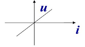
u=Ri (passive sign convention)
-------Ohm’s Law
Since the value of R can range from zero to infinity, it is important that we consider the two extreme possible value of R:
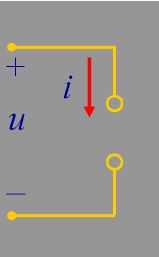
R=0-------is called a short circuit, u=0
注意电流无法确定,不一定为0
R=∞------is called an open circuit, i=0
注意电压不一定为0
Resistance and Conductance:
Resistance is the physical property (or ability) to resist current.
R = ρ l A w h e r e { ρ : r e s i s t i v i t y A : c r o s s − s e c t i o n a l ( 横 截 面 ) l : l e n g t h R=\rho\frac{l}{A} ~where \begin{cases} \rho:resistivity\\ A:cross-sectional(横截面)\\ l:length \end{cases} R=ρAl where⎩⎪⎨⎪⎧ρ:resistivityA:cross−sectional(横截面)l:length
Conductance is the ability of an element to conduct electric current, measured in siemens (S).
G = 1 R = i v G=\frac{1}{R}=\frac{i}{v} G=R1=vi
Resistance and conductance are reciprocals.
R e s i s t o r : { F i x e d V a r i a b l e L i n e a r N o n l i n e a r Resistor: \begin{cases} Fixed\\ Variable\\ Linear\\ Nonlinear \end{cases} Resistor:⎩⎪⎪⎪⎨⎪⎪⎪⎧FixedVariableLinearNonlinear
Fixed: its resistance remains constant. (wirewound type; carbon film type)
Variable: variable resistors have adjustable resistance. (composition type; slider pot)

Linear resistor: obey Ohm’s Law
Nonlinear resistor: does not obey Ohm’s Law
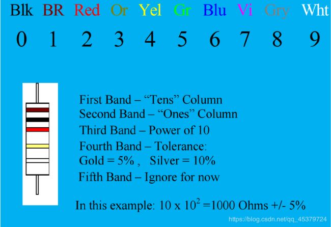
Resistor Color Code
棕1,红2,橙3,黄4,绿5,蓝6,紫7,灰8,白9,黑0
2.3 Nodes,Branches,and Loops
Network topology
Study the properties relating to the placement of elements in the network and the geometric(几何) configuration of the network
1.A branch represents a single element such as a voltage source or a resistor. In other words, branch represents any two-terminal element. ( b )
2.A node is the point of connection between two or more branches. ( n )
3.A loop is any closed path in a circuit with no node passed more than once. ( l )
2.4 Kirchhoff’s Laws
Kirchhoff’s laws form the foundation for circuit analysis
KCL: Kirchhoff’s Current Law (based on the law of conservation of charge)(基尔霍夫电流定律)
支路:每个二端元件(简单支路)
结(节)点:两条或两条以上支路的连接点
复合支路:通过同一电流的分支(简单支路的串联或并联)
广义节点:假定的闭合面
在集总参数电路中,任意时刻,对任意节点流出或流入该节点的代数和等于0
Kirchhoff’s current law (KCL) states that the algebraic sum of currents entering a node (or a closed boundary) is zero.
∑ k = 1 n i k = 0 i 1 + i 2 + ⋯ + i n = 0 \sum\limits_{k=1}^ni_k=0~~~~~~~~i_1+i_2+\cdots+i_n=0 k=1∑nik=0 i1+i2+⋯+in=0
n: the number of branches connected to the node
ik: the kth current entering (or leaving) the node
+: the current entering the node
- : the current leaving the node
An alternative form of KCL:
∑ i i n = ∑ i o u t \sum{i_{in}}=\sum {i_{out}} ∑iin=∑iout
The sum of the currents entering a node is equal to the sum of the currents leaving the node.
A node may be regarded as a closed surface shrunk to a point.
In two dimensions, a closed boundary is the same as a closed path.
说明
- 有多少电荷流入就必须有多少电荷流出(对两边求积分)
- KCL具有普遍适用性:与元件性质和种类无关
- KCL适用于任一结点,也适用于任意假定的闭合面(广义结点)
- KCL方程按照电流的参考方向列写,和电流实际方向无关
KVL: Kirchhoff’s Voltage Law (based on the principle of conservation of energy)
路径:两节点间的通路,由支路组成
回路:由支路组成的闭合路径
网孔:内部不含任何支路的回路
在集总参数电路中,任意时刻,对任意闭合路径,各支路电压的代数和为0
也适用于任意假定的闭合路径
Kirchhoff’s voltage law (KVL) states that the algebraic sum of all voltages around a closed path (or loop) is zero.
∑ k = 1 n u k = 0 u 1 + u 2 + ⋯ + u n = 0 \sum\limits_{k=1}^nu_k=0~~~~~~~~u_1+u_2+\cdots+u_n=0 k=1∑nuk=0 u1+u2+⋯+un=0
n:the number voltages in the loop
The sign on each voltage is the polarity of the terminal encountered first as we travel around the loop.
An alternative form of KVL:
∑ u d r o p s = ∑ u r i s e s \sum u_{drops}=\sum u_{rises} ∑udrops=∑urises
使用时,随意选定回路绕行方向,令压降为+
说明
1) KVL的实质:能量守恒定律–电荷从A点出发绕行
一周回到A点得到或失去的能量为零
2) KVL与元件性质和参数无关
3) KVL方程列写:按电压参考方向,与电压实际方向无关
4) KVL适用于任一回路,也适用于假定闭合路径
Sum of voltage drops=Sum of voltage rises
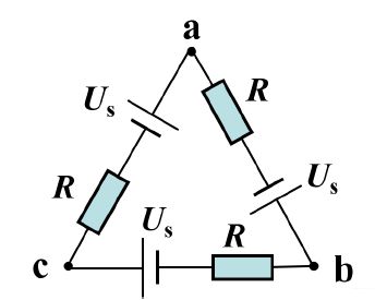
ab两端电压为0,根据KCL,每一个R的电压要等于-Us,R的电压为电源电压的负值
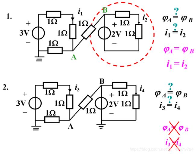
1.中,两个圈分别列KCl可以知道i1=i2=1A,因此中间无电流通过;2.中,
2.5 Series Resistors and Voltage Division
电阻串联,各电阻顺序连接,流过同一电流
总电压等于各串联电阻的电压之代数和
Two or more elements are in series if they are cascaded or connected sequentially and consequently carry the same current.
The equivalent resistance of any number of resistors connected in series is the sum of the individual resistances.
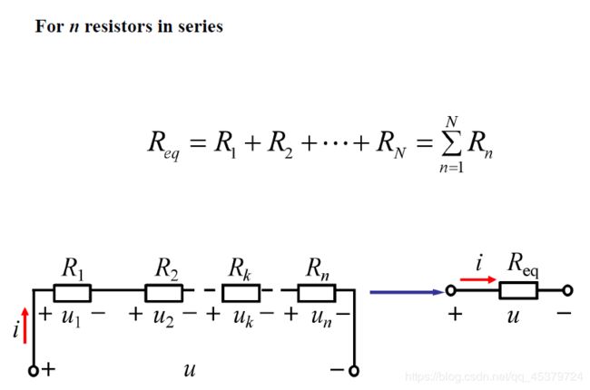
A voltage divider(电压分配)
电压与电阻成正比
R 1 R 2 = U 1 U 2 \frac{R_{1}}{R_{2}}=\frac{U_1}{U_2} R2R1=U2U1
The principle of voltage division:
The voltage u is divided among the resistors in direct proportion(正比) to their resistances.
The kth resistor(Rk) will have a voltage drop of
u k = R k R 1 + R 2 + ⋯ + R n = R k R e q u u_k=\frac{R_k}{R_1+R_2+\cdots+R_n}=\frac{R_k}{R_{eq}}u uk=R1+R2+⋯+RnRk=ReqRku
功率
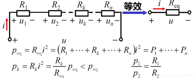
各电阻消耗的功率与电阻大小成正比
总功率等于各串联电阻消耗功率的和
2.6 Parallel Resistors and Current Division
(1) 电压:各电阻两端为同一电压
(2) 电流:总电流等于各并联电阻的电流之代数和
Two or more elements are in parallel if they are connected to the same two nodes and consequently have the same voltage across them.
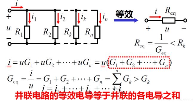
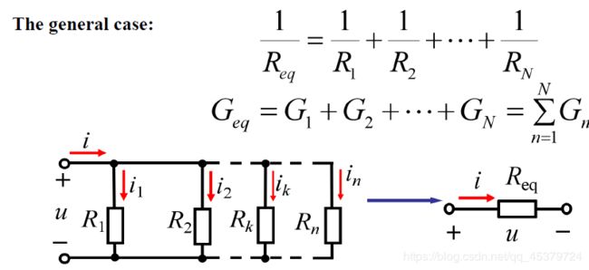
A current divider(电流分配)
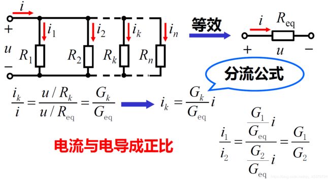
The principle of current division:
The current i is shared by the resistors in inverse proportion to their resistances.
The kth conductor(Gk) will have current
i k = G k G 1 + G 2 + ⋯ + G n i = G k G e q i i_k=\frac{G_k}{G_1+G_2+\cdots +G_n}i=\frac{G_k}{G_{eq}}i ik=G1+G2+⋯+GnGki=GeqGki
功率
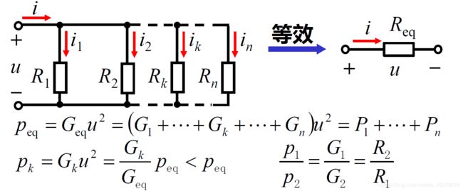
各电阻消耗的功率与电阻大小成反比
总功率等于各并联电阻消耗功率的和
例题
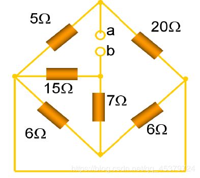
ab等效电阻是10Ω
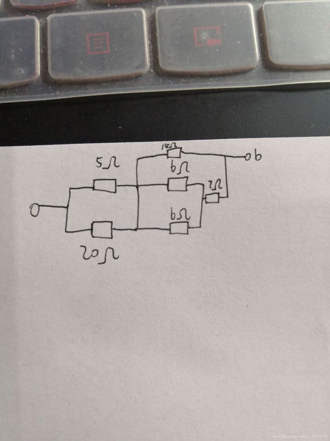
5//20+15//(6//6+7)
本题从a或者b出发画出平面电路都是可以求解的,但是这样做没有灵魂,重点在于定义中的一句话in parallel if they are connected to the same two nodes所以判断并联的关键在于两端相同,画下来的时候直接减一路就对了,因为他们左右是等价的
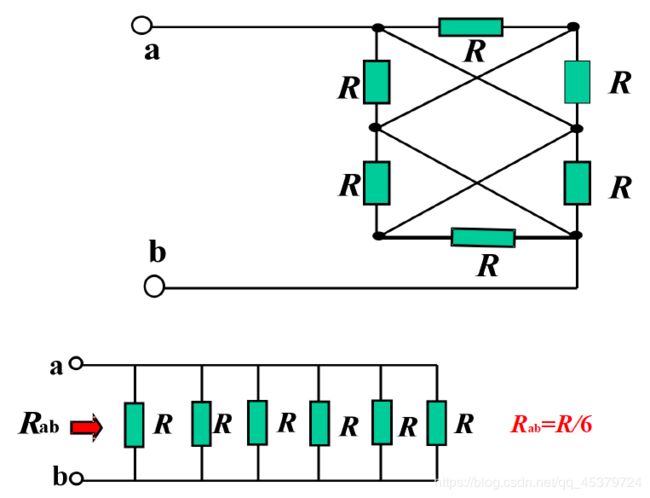
A brigde circuit(桥形连接)
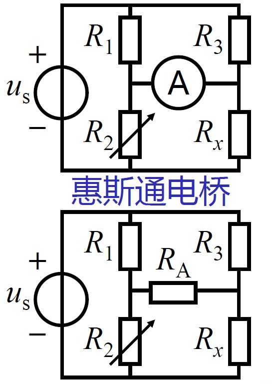
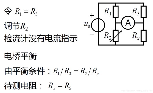
(1) 电阻既不是串联也不是并联,称为桥形连接
(2) R1,R2,R3,Rx所在支路称为桥臂
(3) RA所在支路称为对角线支路
平衡电桥
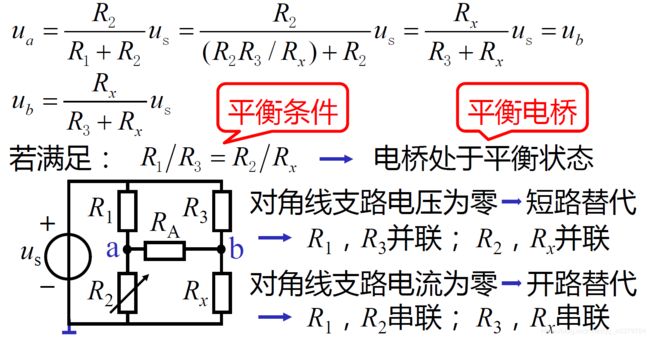
平衡条件:对角线乘积相同
平衡条件有两种替代,一是短路,二是开路
平衡电桥应用(测量电阻)
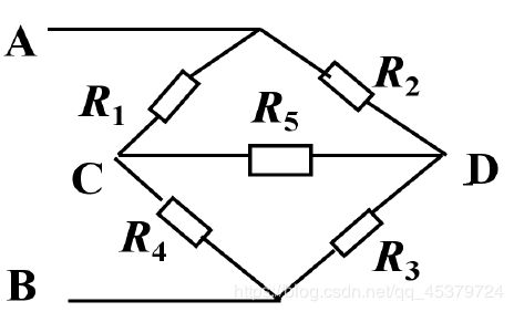
U C D = R 4 R 1 + R 4 U A B − R 3 R 2 + R 3 U A B U_{CD}=\frac{R_4}{R_1+R_4}U_{AB}-\frac{R_3}{R_2+R_3}U_{AB} UCD=R1+R4R4UAB−R2+R3R3UAB
Special case:UCD=0
If R1R3=R2R4, the bridge is balanced.
The resistor R5 can be regarded as short circuit or open circuit.
2.7 Wye_Delta Transformations(Y形连接和Δ形连接)
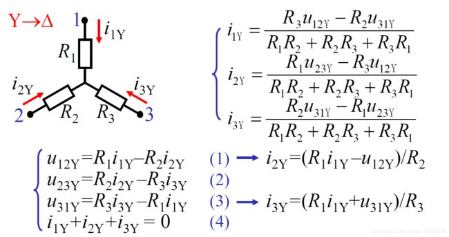
- 连接方式

- Y-Δ等效变换

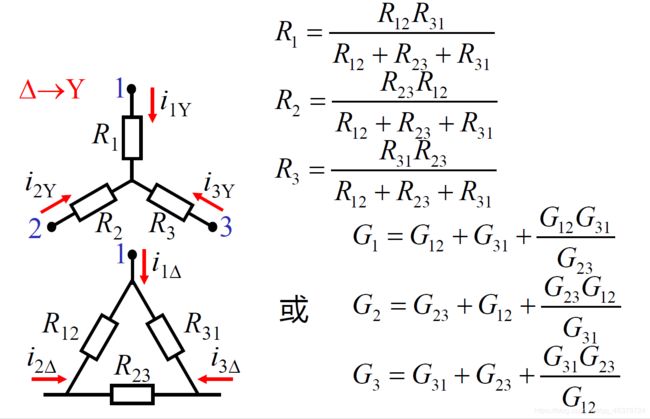
Δ → Y \Delta→Y Δ→Y
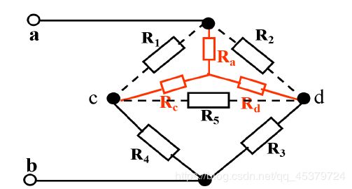
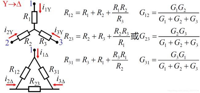
Y → Δ Y→\Delta Y→Δ
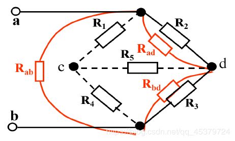
Y–Δ Transformations
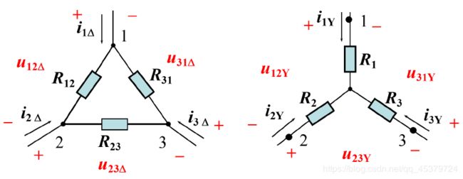
They are equivalent circuits because they exhibit(显示) the same i_v characteristics at the corresponding terminals.
Equivalence condition:
i 1 Δ = i 1 Y , i 2 Δ = i 2 Y , i 3 Δ = i 3 Y u 12 Δ = u 12 Y , u 23 Δ = u 23 Y , u 31 Δ = u 31 Y i_{1\Delta} =i{1Y} , i_{2\Delta} =i{2Y},i_{3\Delta} =i{3Y}\\ u_{12\Delta} =u_{12Y} ,u_{23\Delta} =u_{23Y},u_{31\Delta} =u_{31Y} i1Δ=i1Y,i2Δ=i2Y,i3Δ=i3Yu12Δ=u12Y,u23Δ=u23Y,u31Δ=u31Y

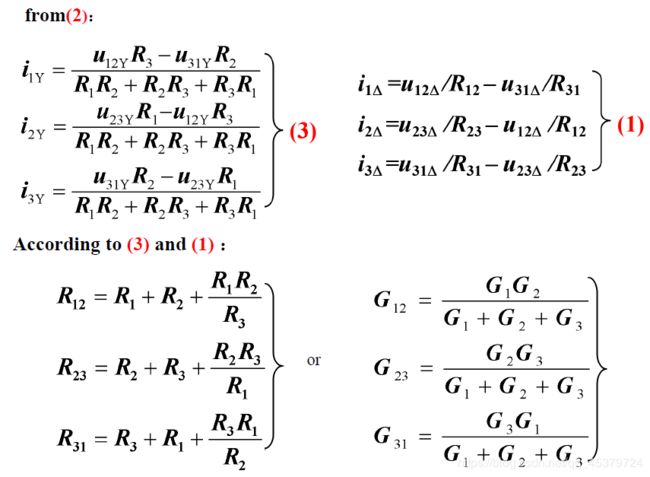
Wye to Delta Conversion(Y→Δ):Each resistor in the Δnetwork is the sum of all possible products of Y resistors taken two at a time, divided by the opposite Y resistor.
Y → Δ { R 12 = R 1 + R 2 + R 1 R 2 R 3 R 23 = R 2 + R 3 + R 2 R 3 R 1 R 31 = R 3 + R 1 + R 3 R 1 R 2 o r { G 12 = G 1 G 2 G 1 + G 2 + G 3 G 23 = G 2 G 3 G 1 + G 2 + G 3 G 31 = G 3 G 1 G 1 + G 2 + G 3 {Y→Δ} \begin{cases} \Large{ R_{12}=R_1+R_2+\frac{R_1R_2}{R_{3}}}\\ \Large{ R_{23}=R_2+R_3+\frac{R_2R_3}{R_{1}}}\\ \Large{ R_{31}=R_3+R_1+\frac{R_3R_1}{R_{2}}}\\ \end{cases} or \begin{cases} \Large{ G_{12}=\frac {G_{1}G_{2}}{G_{1}+G_{2}+G_{3}}}\\ \Large{ G_{23}=\frac {G_{2}G_{3}}{G_{1}+G_{2}+G_{3}}}\\ \Large{ G_{31}=\frac {G_{3}G_{1}}{G_{1}+G_{2}+G_{3}}}\\ \end{cases} Y→Δ⎩⎪⎪⎪⎨⎪⎪⎪⎧R12=R1+R2+R3R1R2R23=R2+R3+R1R2R3R31=R3+R1+R2R3R1or⎩⎪⎪⎪⎨⎪⎪⎪⎧G12=G1+G2+G3G1G2G23=G1+G2+G3G2G3G31=G1+G2+G3G3G1
Delta to Wye Conversion:Each resistor in the Y network is the product of the resistors in the two adjacent Δbranches, divided by the sum of the three Δ resistors.
∆ → Y { R 1 = R 12 R 31 R 12 + R 23 + R 31 R 2 = R 23 R 12 R 12 + R 23 + R 31 R 3 = R 31 R 23 R 12 + R 23 + R 31 o r { G 1 = G 12 + G 31 + G 12 G 31 G 23 G 2 = G 23 + G 12 + G 23 G 12 G 31 G 3 = G 31 + G 23 + G 31 G 23 G 12 {∆→Y} \begin{cases} \Large{ R_1=\frac {R_{12}R_{31}}{R_{12}+R_{23}+R_{31}}}\\ \Large{ R_2=\frac {R_{23}R_{12}}{R_{12}+R_{23}+R_{31}}}\\ \Large{ R_3=\frac {R_{31}R_{23}}{R_{12}+R_{23}+R_{31}}}\\ \end{cases} or \begin{cases} \Large{ G_{1}=G_{12}+G_{31}+\frac {G_{12}G_{31}}{G_{23}}}\\ \Large{ G_{2}=G_{23}+G_{12}+\frac {G_{23}G_{12}}{G_{31}}}\\ \Large{ G_{3}=G_{31}+G_{23}+\frac {G_{31}G_{23}}{G_{12}}}\\ \end{cases} ∆→Y⎩⎪⎪⎪⎨⎪⎪⎪⎧R1=R12+R23+R31R12R31R2=R12+R23+R31R23R12R3=R12+R23+R31R31R23or⎩⎪⎪⎪⎨⎪⎪⎪⎧G1=G12+G31+G23G12G31G2=G23+G12+G31G23G12G3=G31+G23+G12G31G23
特殊情况
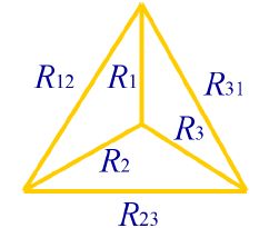
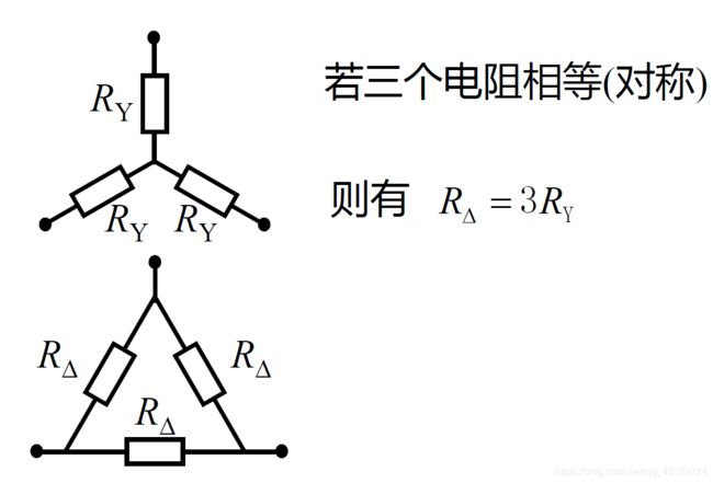
if R12=R23=R31,R1=R2=R3,则RΔ=3RY
2.8 Source Transformation(电源转换## Ideal Voltage Sources**(理想电压源)
In series:u=us1+us2=∑usk
In parallel:u=us1=us2
相同电压源才能并联,各电压源中的电流不确定
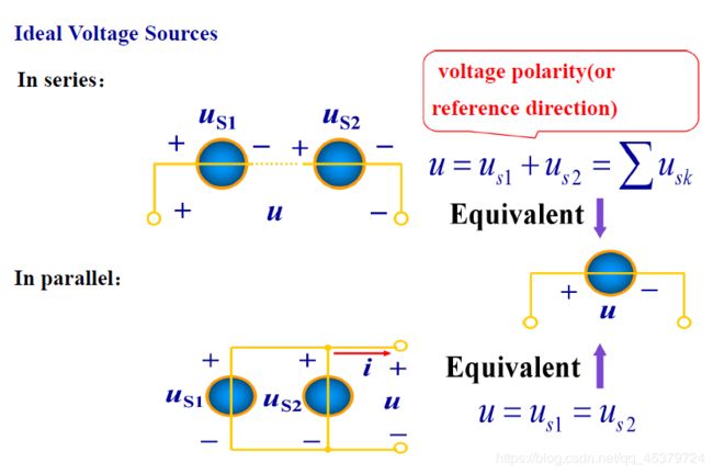
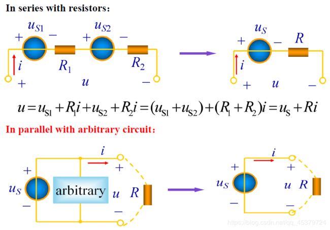
无论是何支路与电压源并联,总可以等效为一个电压源(对外等效)
Ideal Current Sources(理想电流源)
并联:等效为一个电流源(电流等于并联电流源的代数和)
串联:相同电流源才能串联,各电流源的端电压不确定
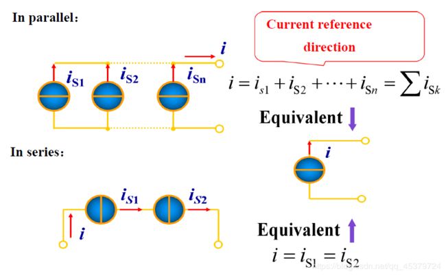
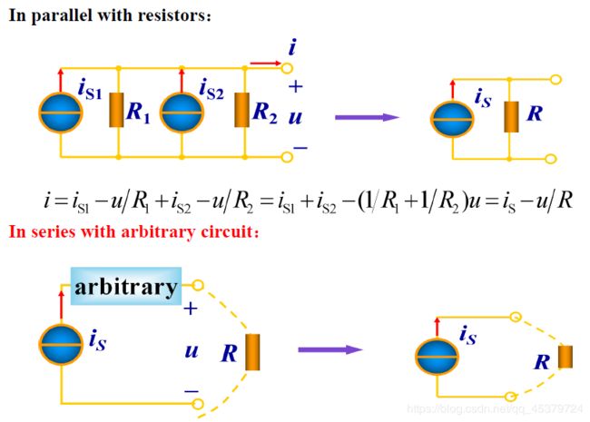
理想电流源与支路的串联:都可以用电流源等效替代
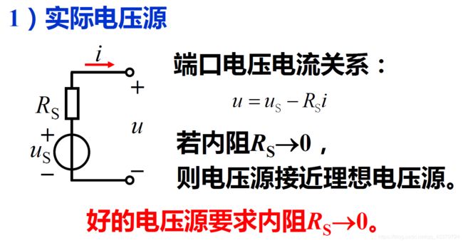
Practical Sources(实际电源)
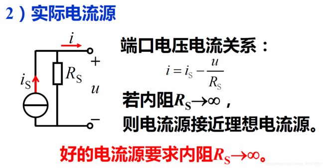
两种实际电源模型的等效变换
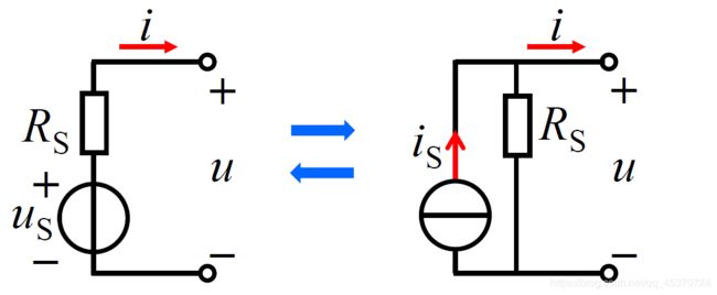
电源变换:理想电压源与电阻的串联电路、理想电流源与电阻的并联电路之间的等效变换。
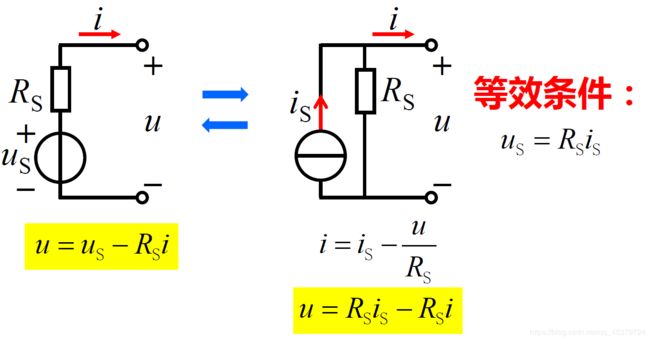
注意
1) 电流源电流方向与电压源电压方向
2) 电阻为零或无穷大时不能变换
Practical Voltage Source: An ideal voltage source in series with a resistor R.
Practical Current Source: An ideal current source in parallel with a resistor R.
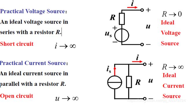
A source transformation is the process of replacing a voltage source in series with a resistor by a current source in parallel with a resistor, or vice versa(或者相反).
The u-i property of the port :
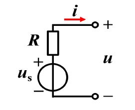
u=us-Ri
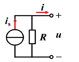
u=(is-i)/G
Source transformation requires
i S = u S R & G = 1 R i_S=\frac{u_S}{R}\&G=\frac{1}{R} iS=RuS&G=R1
2.9 Input Resistance and Equivalent Resistance(输入电阻和等效电阻)
- 一端口
若一个电路向外引出两个端子,且从一个端子流入的电流等于从另一端子流出的电流,则称这一电路为一端口(网络),或二端网络。 - 输入电阻

- 计算方法
若一端口内部仅含电阻,则根据电阻连接形式应用以下方法求电路的等效电阻。
→电阻的串联等效变换
→电阻的并联等效变换
→电阻的Y−∆等效变换
若一端口内部不仅含电阻,还含受控源,用电压比电流法。
→即在端口加电压源,求端口电流,再用端口电压比端口电流。
→或在端口加电流源,求端口电压,再用端口电压比端口电流。
Input resistance (or equivalent resistance) is the resistance between the designated terminals of the network.
The equivalent resistance must exhibit the same i-v characteristics as the original network at the terminals.
Finding Rin
(1) The network has no dependent sources:
➢ turn off all independent sources
➢ series, parallel and Wye_Delta Transformations
(2) The network has dependent sources:
➢ Turn off all independent sources
➢ Dependent sources are not to be turned off
➢ Apply a voltage source at terminals and determine the resulting current (or insert a current source at terminals and find the terminal voltage)