Atmega16的定时器time0
依照AVR使用范例--定时器应用范例http://www.avrvi.com/avr_examples/timer.html。使用ICC application builder快速配置定时器后生成的代码如下:
//ICC-AVR application builder : 2007-8-28 0:55:55
// Target : M16
// Crystal: 7.3728Mhz
#include
#include
void port_init(void)
{
PORTA = 0x00;
DDRA = 0x00;
PORTB = 0x00;
DDRB = 0x00;
PORTC = 0x00;
DDRC = 0x00;
PORTD = 0x00;
DDRD = 0x00;
}
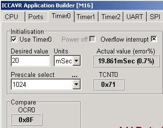
TIMER0 initialize - prescale:1024 /*定时器预分频,预分频由TCCRn的CS02,CS01,CS00确定,详情查看数据手册*/
// WGM: Normal/*定时器,也由TCCRn确定*/
// desired value: 20mSec/*定时器期望设定时间*/
// actual value: 19.861mSec (0.7%)/*定时器实际定时时间,误差比例*/
void timer0_init(void)
{
/*定时器停止,TCCR0寄存器完全控制timer0的运行情况,详细可参考数据手册。*/
TCCR0 = 0x00; //stop
TCNT0 = 0x71; //set count /*定时器寄存器开始值*/
OCR0 = 0x8F; //set compare /*定时器比较值*/
TCCR0 = 0x05; //start timer /*定时器开始*/
}
#pragma interrupt_handler timer0_comp_isr:20
void timer0_comp_isr(void)
{
//compare occured TCNT0=OCR0
}
#pragma interrupt_handler timer0_ovf_isr:10
void timer0_ovf_isr(void)
{
TCNT0 = 0x71; //reload counter value
}
//call this routine to initialize all peripherals
void init_devices(void)
{
//stop errant interrupts until set up
CLI(); //disable all interrupts
port_init();
timer0_init();
MCUCR = 0x00;
GICR = 0x00;
TIMSK = 0x03; //timer interrupt sources
SEI(); //re-enable interrupts
//all peripherals are now initialized
}
下面我们一步一步按顺序来分析。
init_devices()函数首先调用port_init(),初始化端口端口I/O,这个在这里不重要,所以不讨论。然后init_devices()调用timer0_init(),这里我们就应该仔细分析了。主要是各个寄存器的作用。岔开主题,我们所谓的写嵌入式程序,人家说主要就是写寄存器。其实还真是,所以,我们学习嵌入式的时候,就是遇到寄存器的时候,多查数据手册,数据手册才是你找到答案的源泉,再辅以网络的资源,比方说一些比较白话的解释,让你了解得正深刻。现在。我们回到timer0_init()函数中来。
一.Timer/Counter Contro Register – TCCR0 p83

1. Bit 7 – FOC0: Force Output Compare
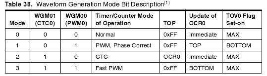
2. Bit 3, 6 – WGM01:0: Waveform Generation Mode
3. Bit 5:4 – COM01:0: Compare Match Output Mode, 当 OC0 连接到物理引脚上时,COM01:0的功能依赖于 WGM01:0 的设置.其中有几个模式表,具体见数据手册。
4. Bit 2:0 – CS02:0: Clock Select

函数timer0_init()中
TCCR0 = 0x00;/*定时器停止,TCCR0寄存器完全控制timer0的运行情况。*/
一般timer0_init()中都需要先让定时器停止的,好设置其他寄存器。
二.Timer/Counter Register – TCNT0 p85
通过 T/C 寄存器可以直接对计数器的 8 位数据进行读写访问。对 TCNT0 寄存器的写访问将在下一个时钟阻止比较匹配。在计数器运行的过程中修改 TCNT0 的数值有可能丢失一次 TCNT0 和 OCR0 的比较匹配。
三.Output Compare Register – OCR0 p85
输出比较寄存器包含一个 8 位的数据,不间断地与计数器数值 TCNT0 进行比较。匹配事
件可以用来产生输出比较中断,或者用来在 OC0 引脚上产生波形。
函数timer0_init()中
TCNT0 = 0x71; //set count 十进制的113
OCR0 = 0x8F; //set compare 十进制的143
为什么得到这两个寄存器的值的呢。先看ICCAVR的application builder
现假设最大计数值为M,timer0为8位,那M=256。(这是我看51的定时器/计数器的基本结构及工作原理,AVR应该差不多的吧,反正我后来用计算器算了一下,符合就得)
计数器初值X的计算式为:
X=M-比较值(计数值)
定时工作方式的计数初值X等于:
X = M - 比较值 = M - t / T = M - (![]() * t) / prescal
* t) / prescal
![]() 为T/C0 最高频率的时钟源,prescal为预分频数。
为T/C0 最高频率的时钟源,prescal为预分频数。
现在我们知道
TCNT0 = 0x71; // set count 十进制的113
OCR0 = 0x8F; // set compare 十进制的143
就相当于OCR0是计数值,TCNT0是初始值。TCNT0=113,那么OCR0=M- TCNT0=143。
我们取![]() =7.3728Mhz,prescal=1024,于是,我们利用公式得出比较值=144,和结果的143有点误差。接着呢,我们试着用公式倒推,算t 。
=7.3728Mhz,prescal=1024,于是,我们利用公式得出比较值=144,和结果的143有点误差。接着呢,我们试着用公式倒推,算t 。
t =(143*1024)/(7.3728*![]() *
*![]() )= 19.86111````ms
)= 19.86111````ms
刚好和设置那里的actual value误差一样。所以说,以倒推的为准取TCNT0和OCR0值
最后呢, TCCR0 = 0x05; //start timer /*定时器开始*/
TCCR0预分频1024,具体可见上图,
应该提醒的是:
8位的定时器timer0根据公式,它最多可以完成35ms的定时任务,1秒的任务它不能完成,所以当想用来定时1秒的时候,只能用16位的定时器了;
且atmega128和atmega16的timer0选择时钟源是不一样的。请千万要注意。现在我们讨论的是atmega16;
还有上边的讨论是在工作模式(waveform mode)选择normal情况下。其他模式初始值和比较值的不一样的,具体你可以选择其他模式看一下它的变化值。
调用了port_init()和timer0_init()两个函数后。我们还有3个寄存器要修改。
一.MCU Control Register – MCUCR P32,68
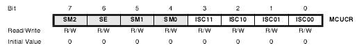
1.Bit 6 – SE: Sleep Enable
2.Bits 7, 5, 4 – SM2..0: Sleep Mode Select Bits 2, 1, and 0
其中几个位的设置见手册P32的Table 13. Sleep Mode Select,如下

3.Bit 1, 0 – ISC01, ISC00: 中断 0 触发方式控制 Bit 1与 Bit 0
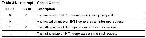
4.Bit 3, 2 – ISC11, ISC10: Interrupt Sense Control 1 Bit 1 and Bit 0
(翻译成“中断触发方式控制 1 Bit1 与 Bit 0”)
其中几个位的设置见手册P68,Bit 3, 2的设置如下图
二.General Interrupt Contro Register – GICR P69,48
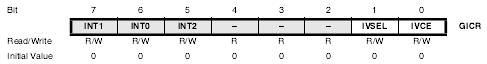
1. Bit 0 – IVCE: Interrupt Vector Change Enable
Bit 1 – IVSEL: Interrupt Vector Select
这两个位只要是跟中断向量的起始地址有关的,现在我们暂时还不需要讨论。
----------------------------------------------------------------
2. Bit 7 – INT1: External Interrupt Request 1 Enable
Bit 6 – INT0: External Interrupt Request 0 Enable
Bit 5 – INT2: External Interrupt Request 2 Enable
三.TIMSK Timer/Counter Interrupt Mask Register – TIMSK p85
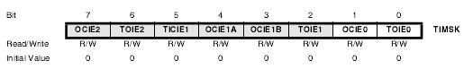
1. Bit 1 – OCIE0: Timer/Counter0 Output Compare Match Interrupt Enapble Bit 0 – TOIE0: Timer/Counter0 Overflow Interrupt Enable p85
2. Bit 5 – TICIE1: Timer/Counter1, Input Capture Interrupt Enable
Bit 4 – OCIE1A: Timer/Counter1, Output Compare A Match Interrupt Enable
Bit 3 – OCIE1B: Timer/Counter1, Output Compare B Match Interrupt Enable
Bit 2 – TOIE1: Timer/Counter1, Overflow Interrupt Enable p116
3. Bit 7 – OCIE2: Timer/Counter2 Output Compare Match Interrupt Enable
Bit 6 – TOIE2: Timer/Counter2 Overflow Interrupt Enable p134
我们现在用Timer/Counter0,所以我们只要设置Bit 1和Bit 0即可, TIMSK = 0x03,即设定允许Timer0比较中断和溢出中断
未完待续`````