AVR 328pb串口基本介绍和使用
AVR 328pb串口基本介绍和使用
-
相关篇《AVR 328pb定时器0基本介绍和使用》
-
基于Atmel Studio 7.0开发环境。
-
结合参考同架构lgt8f328p中文文档:
http://www.prodesign.com.cn/wp-content/uploads/2023/03/LGT8FX8P_databook_v1.0.4.pdf
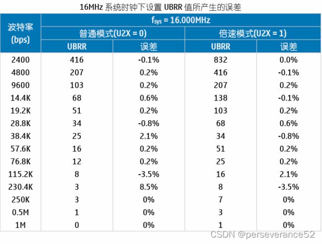
波特率设置及引入误差
对于标准晶振及谐振器频率来说,异步模式下的实际通信的波特率可通过波特率计算公式来
获得,它与常用通信波特率之间的误差可用如下公式来计算:
Error[%] = (Baudreal/Baud – 1)*100%
其中,Baud为常用的通信波特率,Baudreal为通过计算公式算出来的波特率,带入波特率计
算公式即可得到波特率误差与系统时钟fsys和波特率寄存器UBRR值之间的关系如下:
普通模式:
Error[%] = (fsys/(16*(UBRR+1))/Baud – 1)*100%
倍速模式:
Error[%] = (fsys/(8*(UBRR+1))/Baud – 1)*100%
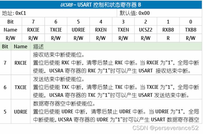
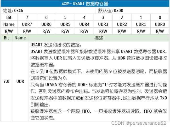
串口相关寄存器定义
-
串口参数代码具体配置:(基于Atmel Studio
GCC C Executable Project裸机开发模式)
#define BAUD 9600
#define F_CPU 16000000UL
#define MYUBRR (F_CPU/16/BAUD-1)

// 串口初始化
void USART0_Init(void)
{
    UCSR0A=(0<<RXC0) | (0<<TXC0) | (0<<UDRE0) | (0<<FE0) | (0<<DOR0) | (0<<UPE0) | (0<<U2X0) | (0<<MPCM0);
    /*Enable receiver and transmitter */
    UCSR0B=(1<<RXCIE0) | (0<<TXCIE0) | (0<<UDRIE0) | (1<<RXEN0) | (1<<TXEN0) | (0<<UCSZ02) | (0<<RXB80) | (0<<TXB80);
    /* Set frame format: 8data, 1stop bit */
    UCSR0C=(0<<UMSEL01) | (0<<UMSEL00) | (0<<UPM01) | (0<<UPM00) | (0<<USBS0) | (1<<UCSZ01) | (1<<UCSZ00) | (0<<UCPOL0);
   /*Set baud rate */
    UBRR0H = (unsigned char)(MYUBRR>>8);
    UBRR0L = (unsigned char)MYUBRR;
       stdout = &mystdout;//输出流配置

    // Ensure that the USART0 is enabled
    PRR0&= ~(1<<PRUSART0);


// Globally enable interrupts
    sei();

}
- 如果波特率倍频(X2):
#define BAUD 9600
#define F_CPU 16000000UL
#define MYUBRR (F_CPU/8/BAUD-1)

// 串口初始化
void USART0_Init(void)
{
// USART0 Baud Rate: 9600 (Double Speed Mode)
    UCSR0A=(0<<RXC0) | (0<<TXC0) | (0<<UDRE0) | (0<<FE0) | (0<<DOR0) | (0<<UPE0) | (1<<U2X0) | (0<<MPCM0);
    /*Enable receiver and transmitter */
    UCSR0B=(1<<RXCIE0) | (0<<TXCIE0) | (0<<UDRIE0) | (1<<RXEN0) | (1<<TXEN0) | (0<<UCSZ02) | (0<<RXB80) | (0<<TXB80);
    /* Set frame format: 8data, 1stop bit */
    UCSR0C=(0<<UMSEL01) | (0<<UMSEL00) | (0<<UPM01) | (0<<UPM00) | (0<<USBS0) | (1<<UCSZ01) | (1<<UCSZ00) | (0<<UCPOL0);

   /*Set baud rate */
    UBRR0H = (unsigned char)(MYUBRR>>8);
    UBRR0L = (unsigned char)MYUBRR;
       stdout = &mystdout;//输出流配置

    // Ensure that the USART0 is enabled
    PRR0&= ~(1<<PRUSART0);


// Globally enable interrupts
    sei();

}
- 串口0数据发送函数:
void USART_Transmit( unsigned char data )
 {
   /* Wait for empty transmit buffer */
   while ( !( UCSR0A & (1<<UDRE0)) )
      ;
   /* Put data into buffer, sends the data */
   UDR0 = data;
 }
- 串口0数据接收函数:
unsigned char USART_Receive( void )
 {
   /* Wait for data to be received */
   while ( !(UCSR0A & (1<<RXC0)) )
      ;
   /* Get and return received data from buffer */
   return UDR0;
 }
printf打印配置内容
- (基于Atmel Studio
GCC C Executable Project裸机开发模式)
#include "util/setbaud.h"
#include "avr/sfr_defs.h"//包含loop_until_bit_is_set函数
// Standard Input/Output functions
#include 串口0中断接收和printf打印例程
- (基于Atmel Studio
GCC C Executable Project裸机开发模式)
/*
* USART0_TEST1.c
*
* Created: 2024/2/2 12:34:43
* Author : Administrator
*/
#include
// USART0 Receiver interrupt service routine串口0接收中断
ISR(USART0_RX_vect)
{
static volatile unsigned char status;
volatile char data;
status = UCSR0A;
data = UDR0;
if ((status & (FRAMING_ERROR | PARITY_ERROR | DATA_OVERRUN))==0)
{
rx_buffer0[rx_counter0++]=data;
if (rx_counter0 > 0&&(rx_buffer0[rx_counter0]==0))
{
// rx_counter0=0;
rx_buffer_overflow0=1;
}
}
}
// 串口初始化
void USART0_Init(void)
{
// USART0 initialization
// Communication Parameters: 8 Data, 1 Stop, No Parity
// USART0 Receiver: On
// USART0 Transmitter: On
// USART0 Mode: Asynchronous
// USART0 Baud Rate: 9600
cli();//关中断
UCSR0A=(0<<RXC0) | (0<<TXC0) | (0<<UDRE0) | (0<<FE0) | (0<<DOR0) | (0<<UPE0) | (0<<U2X0) | (0<<MPCM0);
/*Enable receiver and transmitter */
UCSR0B=(1<<RXCIE0) | (0<<TXCIE0) | (0<<UDRIE0) | (1<<RXEN0) | (1<<TXEN0) | (0<<UCSZ02) | (0<<RXB80) | (0<<TXB80);
/* Set frame format: 8data, 1stop bit */
UCSR0C=(0<<UMSEL01) | (0<<UMSEL00) | (0<<UPM01) | (0<<UPM00) | (0<<USBS0) | (1<<UCSZ01) | (1<<UCSZ00) | (0<<UCPOL0);
/*Set baud rate */
// UBRR0H=0x00;
// UBRR0L=0x67;//9600
UBRR0H = (unsigned char)(MYUBRR>>8);
UBRR0L = (unsigned char)MYUBRR;
// Ensure that the USART0 is enabled
PRR0&= ~(1<<PRUSART0);
stdout = &mystdout;
// Globally enable interrupts
sei();
}
int main(void)
{
/* Replace with your application code */
CLKPR=(1<<CLKPCE);
CLKPR=(0<<CLKPCE) | (0<<CLKPS3) | (0<<CLKPS2) | (0<<CLKPS1) | (0<<CLKPS0);
DDRB = PINB5;//配置PB5为输出模式
USART0_Init();
printf("Hello World!\r\n");
while (1)
{
if (rx_buffer_overflow0)
{
rx_counter0 =0;
rx_buffer_overflow0 =0;
printf("%s\r\n",rx_buffer0);
memset(rx_buffer0,0,sizeof(rx_buffer0));
}
PORTB ^= (1 << PINB5);//PB5状态翻转
_delay_ms(1000);
}
}
Atmel Studio Atmel Start Project开发模式工程
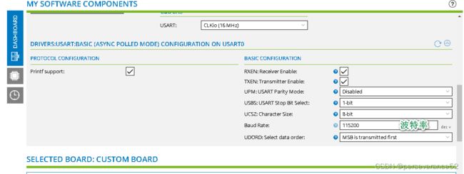
✨如果基于Atmel Start Project创建对应的串口外设工程,那么开发方式如同STM32使用STM32CubeMX来配置工程并开发,相对于使用纯裸机自行配置寄存器开发方式要简单易上手一些。不需要掌握具体外设对应的寄存器如何配置信息。
配置流程
- 串口初始化函数:
USART_0_initialization();
/* configure pins and initialize registers */
void USART_0_initialization(void)
{

	// Set pin direction to input
	PD0_set_dir(PORT_DIR_IN);

	PD0_set_pull_mode(
	    //  Pull configuration
	    //  pad_pull_config
	    //  Off
	    //  Pull-up
	    PORT_PULL_OFF);

	// Set pin direction to output
	PD1_set_dir(PORT_DIR_OUT);

	PD1_set_level(
	    //  Initial level
	    //  pad_initial_level
	    //  Low
	    //  High
	    false);

	USART_0_init();
}
/**
* \brief Initialize USART interface
* If module is configured to disabled state, the clock to the USART is disabled
* if this is supported by the device's clock system.
*
* \return Initialization status.
* \retval 0 the USART init was successful
* \retval 1 the USART init was not successful
*/
int8_t USART_0_init()
{
// Module is in UART mode
/* Enable USART0 */
PRR0 &= ~(1 << PRUSART0);
#define BAUD 115200
#include
- 通过
Atmel Start Project创建的工程,配置的所有外设初始化都在atmel_start_init();函数中被一起初始化。
- 测试代码:
#include 


