Camera5 MTK camera驱动框架介绍
一、概序:
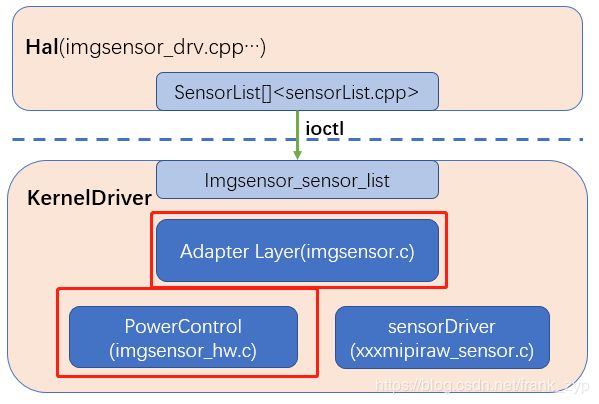
前文已经介绍了camera驱动部分的内容Camera4 MTK camera驱动结构介绍,这里在回顾下之前的框架图,
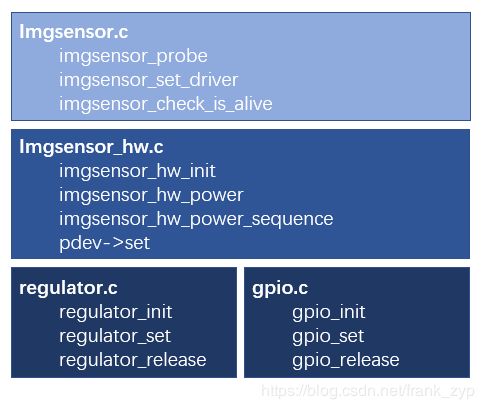
imgsensor起到承上启下的作用,在系统起来时会创建整个camera驱动运行的环境,其中主要的
文件和函数如下框图所示,先设备挂载时会调用注册platform设备platform_driver_register,在匹配成
功后会调用probe函数进行初始相关的设备:
其中camera的三路电压的上电方式可以通过GPIO来控制,也可以通过PMIC(REGULATOR)的方式来
进行控制,在imgsensor_hw中通过不同的pdev信息,调用不同的set函数。涉及的文件路径:
kernel-4.9/drivers/misc/mediatek/imgsensor/src/common/v1/imgsensor.c
kernel-4.9/drivers/misc/mediatek/imgsensor/src/common/v1/imgsensor_hw.c
kernel-4.9/drivers/misc/mediatek/imgsensor/src/mt6765/camera_hw/regulator/regulator.c
kernel-4.9/drivers/misc/mediatek/imgsensor/src/mt6765/camera_hw/gpio/gpio.c
二、上电相关的结构体之间的联系:
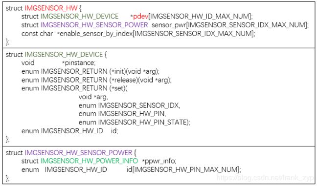
(1)IMGSENSOR_HW结构体:
IMGSENSOR_HW结构体包含了pdev(gpio/regulator)的设备结构体和上电时序相关的结构体:
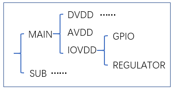
(2)上电时序控制相关:
上电方式控制:GPIO?REGULATOR?
上电时序控制结构体:
三、系统初始化:
1、设备加载:
imgsensor和其他的驱动模块相同,也是通过module_init来初始化模块,在init中注册platform总线驱动,
从而需要对应的platform_driver结构体信息:
static const struct of_device_id gimgsensor_of_device_id[] = {
	{ .compatible = "mediatek,camera_hw", },
	{}
};

static struct platform_driver gimgsensor_platform_driver = {
	.probe      = imgsensor_probe,
	.remove     = imgsensor_remove,
	.suspend    = imgsensor_suspend,
	.resume     = imgsensor_resume,
	.driver     = {
		.name   = "image_sensor",
		.owner  = THIS_MODULE,
#ifdef CONFIG_OF
		.of_match_table = gimgsensor_of_device_id,
#endif
	}
};
当gimgsensor_of_device_id的信息在dts中match上以后回执行到对应的probe函数,probe中主要注册
了sensordrv的字符设备和初始化imgsensor的硬件信息(时钟及上电):
static int imgsensor_probe(struct platform_device *pdev)
{
	/* Register char driver */
	imgsensor_driver_register();

	gpimgsensor_hw_platform_device = pdev;

	imgsensor_clk_init(&pgimgsensor->clk);
	imgsensor_hw_init(&pgimgsensor->hw);
	imgsensor_i2c_create();
	imgsensor_proc_init();

	atomic_set(&pgimgsensor->imgsensor_open_cnt, 0);
	return 0;
}
2、imgsensor_driver_register创建字符设备:
//字符设备的file_operation结构体
static const struct file_operations gimgsensor_file_operations = {
	.owner = THIS_MODULE,
	.open = imgsensor_open,
	.release = imgsensor_release,
	.unlocked_ioctl = imgsensor_ioctl,
#ifdef CONFIG_COMPAT
	.compat_ioctl = imgsensor_compat_ioctl
#endif
};

static inline int imgsensor_driver_register(void){
    //分配一个设备号和nanme
    alloc_chrdev_region(&dev_no, 0, 1, IMGSENSOR_DEV_NAME)

	/* Allocate driver */
	gpimgsensor_cdev = cdev_alloc();

	/* Attatch file operation. */
	cdev_init(gpimgsensor_cdev, &gimgsensor_file_operations);

	/* Add to system */
	cdev_add(gpimgsensor_cdev, dev_no, 1);

	gpimgsensor_class = class_create(THIS_MODULE, "sensordrv");

	device_create(gpimgsensor_class, NULL, dev_no, NULL, IMGSENSOR_DEV_NAME);
}
3、imgsensor_clk_init 时钟初始化:
enum IMGSENSOR_RETURN imgsensor_clk_init(struct IMGSENSOR_CLK *pclk)
{
	int i;
	struct platform_device *pplatform_dev = gpimgsensor_hw_platform_device;

	/* get all possible using clocks */
	for (i = 0; i < IMGSENSOR_CCF_MAX_NUM; i++)
		pclk->imgsensor_ccf[i] =
		    devm_clk_get(&pplatform_dev->dev, gimgsensor_mclk_name[i]);

	return IMGSENSOR_RETURN_SUCCESS;
}
4、imgsensor_hw_init电压初始化:
(1)依次调用GPIO/REGULATOR/MCLK的init接口;
(2)解析出imgsensor_custom_config,获取到对应sensor的对应管脚(DVDD/AVDD...)的上电方式(GPIO/REGULATOR);
enum IMGSENSOR_RETURN imgsensor_hw_init(struct IMGSENSOR_HW *phw)
{
	struct IMGSENSOR_HW_SENSOR_POWER      *psensor_pwr;
	struct IMGSENSOR_HW_CFG               *pcust_pwr_cfg;
	struct IMGSENSOR_HW_CUSTOM_POWER_INFO *ppwr_info;
	int i, j;
	char str_prop_name[LENGTH_FOR_SNPRINTF];
	struct device_node *of_node
		= of_find_compatible_node(NULL, NULL, "mediatek,camera_hw");
        //依次调用GPIO/REGULATOR/MCLK的init接口;
	for (i = 0; i < IMGSENSOR_HW_ID_MAX_NUM; i++) {
		if (hw_open[i] != NULL)
			(hw_open[i])(&phw->pdev[i]);

		if (phw->pdev[i]->init != NULL)
			(phw->pdev[i]->init)(phw->pdev[i]->pinstance);
	}
        //解析出imgsensor_custom_config
	for (i = 0; i < IMGSENSOR_SENSOR_IDX_MAX_NUM; i++) {
		psensor_pwr = &phw->sensor_pwr[i];

		pcust_pwr_cfg = imgsensor_custom_config;//上电时序
		while (pcust_pwr_cfg->sensor_idx != i)
			pcust_pwr_cfg++;

		//退出循环
		if (pcust_pwr_cfg->sensor_idx == IMGSENSOR_SENSOR_IDX_NONE)
			continue;

		//ppwr_info对应{IMGSENSOR_HW_ID_GPIO, IMGSENSOR_HW_PIN_AVDD}
		ppwr_info = pcust_pwr_cfg->pwr_info;

		while (ppwr_info->pin != IMGSENSOR_HW_PIN_NONE) {
			//查询imgsensor_custom_config中ID_PIN 是否在GPIO/REGULATOR/Mclk中?
			for (j = 0; j < IMGSENSOR_HW_ID_MAX_NUM; j++){
				if (ppwr_info->id == phw->pdev[j]->id)
					break;
			 }
			//将对应sensor的对应PIN(DVDD/AVDD...)设置为系统的ID_PIN(GPIO/REGULATOR/MCKL)
			psensor_pwr->id[ppwr_info->pin] = j;
			ppwr_info++;
		}
	}

	//判断dts中是否设定对应的index为对应的name,如:cam3_enable_sensor = "gc2375hmain3_mipi_raw";
	for (i = 0; i < IMGSENSOR_SENSOR_IDX_MAX_NUM; i++) {
		memset(str_prop_name, 0, sizeof(str_prop_name));
		snprintf(str_prop_name,
					sizeof(str_prop_name),
					"cam%d_%s",
					i,
					"enable_sensor");
		if (of_property_read_string(
			of_node,
			str_prop_name,
			&phw->enable_sensor_by_index[i]) < 0) {
			pr_info("Property cust-sensor not defined\n");
			phw->enable_sensor_by_index[i] = NULL;
		}
	}
	return IMGSENSOR_RETURN_SUCCESS;
}
5、imgsensor_i2c_create I2C设备初始化:
enum IMGSENSOR_RETURN imgsensor_i2c_create(void)
{
	int i;

	for (i = 0; i < IMGSENSOR_I2C_DEV_MAX_NUM; i++)
		i2c_add_driver(&gi2c_driver[i]);

	return IMGSENSOR_RETURN_SUCCESS;
}
6、具体类型的上电介绍(以pmic控制的regulator方式为例)
前面imgsensor_hw_init中有去调用imgsensor_hw_regulator_open和regulator_init:
(1)传入对应的设备的device结构体:
static struct IMGSENSOR_HW_DEVICE device = {
	.pinstance = (void *)®_instance,
	.init      = regulator_init,//开机初始化时调用
	.set       = regulator_set,//在上电设置电压时会调用
	.release   = regulator_release,
	.id        = IMGSENSOR_HW_ID_REGULATOR
};

enum IMGSENSOR_RETURN imgsensor_hw_regulator_open(
	struct IMGSENSOR_HW_DEVICE **pdevice)
{
	*pdevice = &device;
	return IMGSENSOR_RETURN_SUCCESS;
}
(2)调用对应的init进行初始化:
因为MTK 平台的PMIC上电是通过统一的REGULATOR进行统一管理的,每一种上电方式需要申请对应type
的regulator控制的结构体,才可以来进行设置:
enum REGULATOR_TYPE {
	REGULATOR_TYPE_VCAMA,
	REGULATOR_TYPE_VCAMD,
	REGULATOR_TYPE_VCAMIO,
	REGULATOR_TYPE_MAX_NUM
};

static enum IMGSENSOR_RETURN regulator_init(void *pinstance)
{
	struct REGULATOR *preg = (struct REGULATOR *)pinstance;
	struct device            *pdevice;
	struct device_node       *pof_node;
	int j, i;
	char str_regulator_name[LENGTH_FOR_SNPRINTF];

	pdevice  = gimgsensor_device;

	for (j = IMGSENSOR_SENSOR_IDX_MIN_NUM;j < IMGSENSOR_SENSOR_IDX_MAX_NUM;j++) {
		for (i = 0; i < REGULATOR_TYPE_MAX_NUM; i++) {
			snprintf(str_regulator_name,
				sizeof(str_regulator_name),
				"cam%d_%s", j,
				regulator_control[i].pregulator_type);
			preg->pregulator[j][i] =
			    regulator_get(pdevice, str_regulator_name);

			if (preg->pregulator[j][i] == NULL)
				pr_err("regulator[%d][%d]  %s fail!\n",
					j, i, str_regulator_name);

			atomic_set(&preg->enable_cnt[j][i], 0);
		}
	}
	pdevice->of_node = pof_node;
	imgsensor_oc_init();
	return IMGSENSOR_RETURN_SUCCESS;
}
到这里imgsensor部分的内容还有对上(hal层)承接的ioctl相关的内容没有介绍,这部分的内容会在后续的
整个系统调用流程中进行梳理。
作者:frank_zyp
您的支持是对博主最大的鼓励,感谢您的认真阅读。
本文无所谓版权,欢迎转载。


