<一> graphviz dot 使用步骤
- 安装graphviz
brew install graphviz(mac os x系统) - 创建文本文件并命名为*.dot, 编写dot脚本
- 在第二部创建的文件中编写脚本
- 编译脚本, 输出图片
- 编译命令:
dot -Tpng *.dot -o *.png - 记得把
*换成具体的文件名, 这样你就成功的用脚本渲染出你要绘制的图片啦
- 编译命令:
<二> graphviz dot语言相关知识
- 注释
- 使用双斜杠注释
- 有向图
- 使用
digraph定义有向图 - 使用
->表述节点之间的关系 - 如:
```dot
digraph g {
    a->b;
    b->c;
    c->a;
}
```
效果如下:
- 无向图
- 使用
graph定义无向图 - 使用
--表述节点之间的关系 - 节点之间的关系
- 表述节点直接的关系如下:
- 有向图:
a -> b, a节点指向b节点 - 无像图:
a -- b, a节点与b节点连通
- 有向图:
- 定义节点属性
- 定义属性, 格式为:
node[attribute1=value1, attribute2=value2] - 如:
```
//定义a节点为长方形, 节点显示的文本为"Hello world"样式为填充, 填充颜色为#ABACBA
a[shape=box,label="Hello world",style=filled,fillcolor="#ABACBA"];
```
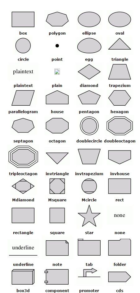
- 各种形状请参考下面第7条
- 定义关系属性(即连接两个节点之间的线的样式)
- 定义节点的形状
- 栗子:
```dot
  //定义节点属性
  digraph g {
      //==========定义节点关系============
      a->b;
      b->c;
      c->a;
      c->d->e->f;
      d->g;
      e->h;
      //==========定义节点属性============
      //定义a节点为长方形, 样式为填充, 填充颜色为#ABACBA
      a[shape=box,label="Server1\nWebServer",fillcolor="#ABACBA",style=filled];
      //定义b为5边形, 标签为"bb", 样式为填充, 填充色为red
      b[shape=polygon,sides=5,label="bb",style=filled,fillcolor=red];
      //c, 默认为椭圆
      d[shape=circle]; //园
      e[shape=triangle]; //三角形
      f[shape=polygon, sides=4, skew=0.5]; //平行四边形
      g[shape=polygon, distortion=0.5]; //梯形, 上边长
      h[shape=polygon, distortion=-.5]; //梯形, 下边长
  }
```
 效果如下:
- 哈希表(hash table)
```
digraph g {
nodesep = .5;
rankdir = LR; //指定绘图的方向 (LR从左到右绘制)
//定义竖直节点
node[shape=record, width=.1, height=.1];
node0[label=" | | | | | | ", height=2.5]; //我是一个属性, 我有7个属性
//定义横向节点
node[width=1.5];
node1[label="{ a13 | 111 | }"]; //我也是一个节点, 定义了3个属性
node2[label="{ hello | 2387 | }"];
node3[label="{ g23 | 344 | }"];
node4[label="{ k535 | 246 | }"];
node5[label="{ h25 | 13 | }"];
node6[label="{ dj | 04 | }"];
node7[label="{ sbd | 0x543 | }"];
//建立节点之间的联系
node0:f0 -> node1:n;
node0:f1 -> node2:n;
node0:f2 -> node3:n;
node0:f5 -> node4:n;
node0:f6 -> node5:n;
node2:p -> node6:n;
node4:p -> node7:n;
}
```
效果如下:

- 更多形状
* 请参考[官方文档](http://www.graphviz.org/Documentation.php)
* 或者下面
- 定义结构
- 一个简单的数据结构示例
digraph g { node[shape=record,height=.1]; //定义了下面的node样式 node0[label="| A| "]; //我是一个node, 我有三个属性, 第二个属性名字为A, 其他两个为空 node1[label=" | B| "]; node2[label=" | C| "]; node3[label=" | D| "]; node4[label=" | E| "]; node5[label=" | F| "]; node6[label=" | H| "]; node7[label=" | I| "]; node8[label=" | J| "]; node9[label=" | K| "]; "node0":f2 -> "node1": f1; //node0的第三个属性连到node1的第二个属性 "node1":f0 -> "node2": f1; "node1":f1 -> "node3": f2; "node3":f0 -> "node4": f0; "node3":f1 -> "node5": f1; "node3":f2 -> "node6": f2; "node6":f1 -> "node7": f1; "node7":f1 -> "node8": f0; "node2":f2 -> "node9": f1; } 效果如下:
使用node定义结构, node[shape=record]
-
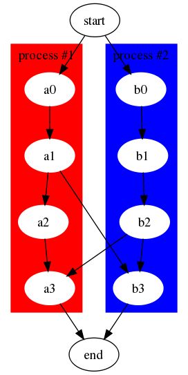
使用subgraph定义子图
digraph g {
    //定义一个子图, subgraph定义子图
    subgraph cluster0 {
        node[style=filled, color=white];  //定义子图中的节点的样式
        style=filled; //定义子图的样式
        color=red; //定义子图的填充色
        a0->a1->a2->a3; //定义节点, 及节点之间的关系
        label="process #1"; //定义子图的标签
     }

   //又定义一个子图
   subgraph cluster1 {
      node[style=filled, color=white];
      style=filled;
      color=blue; //定义子图的填充色
      b0->b1->b2->b3; //定义节点及其关系
      label="process #2";
      labelColor=white;
   }

    //定义子图之间的关系
    start->a0;
    start->b0;
    a1->b3;
    b2->a3;
    a3->end;
    b3->end;
}
效果如下:
更多结构请参考官方文档
-
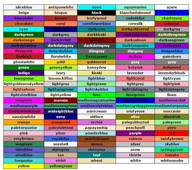
常用颜色如下:
- 定义关系的样式(节点之间的连线的样式)
-
有向图
digraph g {
  //edge[style=dashed]; //定义边的样式, 虚线
  node[peripheries=2, style=filled, color="#eecc80"];
  a->b [color=red, style=dashed]; //定义边的颜色, 红色 (b和方括号之间必须有空格)
  b->c; //箭头, 三角形; 箭尾, 菱形
  b->d [arrowhead=box]; //箭头, 长方形
  b->e [dir=none]; //没有箭头
  d->f [dir=both]; //双向箭头
  f->h [label=go]; //定义edge的标签
  f->k [arrowhead=diamond]; //更改箭头形状 (更多箭头形状请参考官方文档: http://www.graphviz.org/content/arrow-shapes)
  k->y [headlabel="哈哈", taillabel="洗洗"];
}
效果如下:
-
无向图
 graph g {
  edge[style=dashed]; //定义边的样式, 虚线
  a -- b [color=red]; //定义边的颜色, 红色 (b和方括号之间必须有空格)
}
效果如下:
-
references:
graphviz官网
graphviz文档地址
dot官方文档
使用graphviz绘制流程图


