基于ProjectQ平台的deutsch算法demo
推荐量子计算科普:http://tech.sina.com.cn/d/2017-08-31/doc-ifykpysa2199081.shtml
01 基本信息及生成本地文档
ProjectQ是基于python的开源量子计算框架。易用性较好。
源码地址:https://github.com/ProjectQ-Framework/ProjectQ.git
官网声明支持python2.7/3.4/3.5/3.6。
基本安装方法:(如果中途出错,可能是因为下载超时,多运行几次命令即可)
pip install projectq
下载方式(如果安装过git):
git clone https://github.com/ProjectQ-Framework/ProjectQ.git
下载的源码里面有丰富的文档说明ProjectQ\docs,这个文档需要本地编译以下。具体方法,可以参考:https://github.com/ProjectQ-Framework/ProjectQ/blob/develop/docs/README.rst
运行如下命令安装并生成projectq本地文档。比较详细。支持多种格式。
python -m pip install sphinx
python -m pip install sphinx_rtd_theme
:: docs当前目录下生成 html文档
make html
:: 在当前目录下生成 singlehtml 文档
:: ProjectQ\docs\_build\html\index.html
::
make singlehtml
:: ProjectQ\docs\_build\singlehtml\index.html
:: 在当前目录下生成 epub 类型文档
::
make epub
:: ProjectQ\docs\_build\epub\ProjectQ.epub
pdflatex
如果要依托python脚本生成电路图,需要latex转pdf或者其它格式的工具,projectq推荐的工具是pdflatex。windows上面需要安装 MiKTex。下载地址: https://miktex.org/download 。我适用的是basic-miktex-2.9.7031-x64.exe
关于生成电路图的demo,可以参考:ProjectQ\examples\gate_zoo.py。(注意需要安装pdflatex。否则只能生成latex文件。)
先运行 gate_zoo.py文件,在当前目录下生成zoo.tex。
再在cmd窗口运行 pdflatex zoo.tex,会提示安装一些pdflatex的依赖。一次安装即可(如果依赖下载/安装失败,会一直提示安装,多次点击安装即可)。然后即可在当前目录下生成 zoo.pdf。

02 基与ProjectQ的 Deutsch算法实现
这个demo代码来自《量子算法与编程入门》4.1.3节 ProjectQ
代码稍微做了python部分的修改,没修改量子算法相关内容。
deutsch.py
import sys
import math
import projectq.setups.ibm
from projectq.backends import IBMBackend, CircuitDrawer
from projectq import MainEngine
from projectq.ops import *

def Deutsch(eng, t):
    qs = eng.allocate_qureg(2)
    X | qs[1]
    All(H) | qs
    CNOT | (qs[0], qs[1])
    H | qs[0]
    All(Measure) | qs
    eng.flush()
    if t == 'ibm':
        results = eng.backend.get_probabilities(qs)
    elif t == 'simulator':
        print("执行Deutsch算法,测量得到的结果是:" + str(int(qs[0])))
    elif t == 'drawer':
        print(drawing_engine.get_latex())
        s = drawing_engine.get_latex()
        prefix = 'deutsch'
        with open('{}.tex'.format(prefix), 'w') as f:
            f.write(s)
    else:
        pass

# 如下运行
# D:/git/Quantum/ProjectQ/examples/deutsch.py drawer
# 运行绘制电路图类型,会在当前目录下生成 deutsch.tex文件
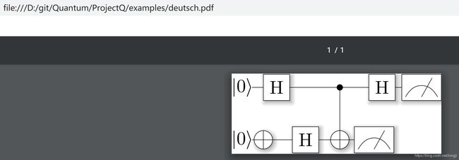
# 在运行pdflatex deutsch.tex 生成电路图的pdf文件deutsch.pdf
# pdflatex deutsch.tex
# D:/git/Quantum/ProjectQ/examples/deutsch.py ibm
# D:/git/Quantum/ProjectQ/examples/deutsch.py simulator
# D:/git/Quantum/ProjectQ/examples/deutsch.py
if __name__ == "__main__":
    if len(sys.argv) == 1:
        types = 'simulator'
    else:
        types = sys.argv[1]

    if types == 'ibm':
        # ibm backend
        eng = MainEngine(IBMBackend(use_hardware=True, num_runs=1024, verbose=True, device="ibmqx4"))
    elif types == 'simulator':
        eng = MainEngine()
        types = 'simulator'
    elif types == 'drawer':
        drawing_engine = CircuitDrawer()
        eng = MainEngine(drawing_engine)
    else:
        eng = MainEngine()
        types = 'simulator'

    Deutsch(eng, types)
运行ibm物理芯片上,需要设置账号。
这里测试本地模拟器生成电路图方式。运行结果如下:
D:/git/Quantum/ProjectQ/examples/deutsch.py drawer
C:\Python36\python.exe D:/git/Quantum/ProjectQ/examples/deutsch.py drawer
\documentclass{standalone}
\usepackage[margin=1in]{geometry}
\usepackage[hang,small,bf]{caption}
\usepackage{tikz}
\usepackage{braket}
\usetikzlibrary{backgrounds,shadows.blur,fit,decorations.pathreplacing,shapes}

\begin{document}
\begin{tikzpicture}[scale=0.8, transform shape]

\tikzstyle{basicshadow}=[blur shadow={shadow blur steps=8, shadow xshift=0.7pt, shadow yshift=-0.7pt, shadow scale=1.02}]\tikzstyle{basic}=[draw,fill=white,basicshadow]
\tikzstyle{operator}=[basic,minimum size=1.5em]
\tikzstyle{phase}=[fill=black,shape=circle,minimum size=0.1cm,inner sep=0pt,outer sep=0pt,draw=black]
\tikzstyle{none}=[inner sep=0pt,outer sep=-.5pt,minimum height=0.5cm+1pt]
\tikzstyle{measure}=[operator,inner sep=0pt,minimum height=0.5cm, minimum width=0.75cm]
\tikzstyle{xstyle}=[circle,basic,minimum height=0.35cm,minimum width=0.35cm,inner sep=-1pt,very thin]
\tikzset{
shadowed/.style={preaction={transform canvas={shift={(0.5pt,-0.5pt)}}, draw=gray, opacity=0.4}},
}
\tikzstyle{swapstyle}=[inner sep=-1pt, outer sep=-1pt, minimum width=0pt]
\tikzstyle{edgestyle}=[very thin]

\node[none] (line0_gate0) at (0.1,-0) {$\Ket{0}$};
\node[none] (line0_gate1) at (0.5,-0) {};
\node[none,minimum height=0.5cm,outer sep=0] (line0_gate2) at (0.75,-0) {};
\node[none] (line0_gate3) at (1.0,-0) {};
\draw[operator,edgestyle,outer sep=0.5cm] ([yshift=0.25cm]line0_gate1) rectangle ([yshift=-0.25cm]line0_gate3) node[pos=.5] {H};
\draw (line0_gate0) edge[edgestyle] (line0_gate1);
\node[none] (line1_gate0) at (0.1,-1) {$\Ket{0}$};
\node[xstyle] (line1_gate1) at (0.5,-1) {};
\draw[edgestyle] (line1_gate1.north)--(line1_gate1.south);
\draw[edgestyle] (line1_gate1.west)--(line1_gate1.east);
\draw (line1_gate0) edge[edgestyle] (line1_gate1);
\node[none] (line1_gate2) at (1.05,-1) {};
\node[none,minimum height=0.5cm,outer sep=0] (line1_gate3) at (1.3,-1) {};
\node[none] (line1_gate4) at (1.55,-1) {};
\draw[operator,edgestyle,outer sep=0.5cm] ([yshift=0.25cm]line1_gate2) rectangle ([yshift=-0.25cm]line1_gate4) node[pos=.5] {H};
\draw (line1_gate1) edge[edgestyle] (line1_gate2);
\node[xstyle] (line1_gate5) at (1.9500000000000002,-1) {};
\draw[edgestyle] (line1_gate5.north)--(line1_gate5.south);
\draw[edgestyle] (line1_gate5.west)--(line1_gate5.east);
\node[phase] (line0_gate4) at (1.9500000000000002,-0) {};
\draw (line0_gate4) edge[edgestyle] (line1_gate5);
\draw (line1_gate4) edge[edgestyle] (line1_gate5);
\draw (line0_gate3) edge[edgestyle] (line0_gate4);
\node[none] (line0_gate5) at (2.5000000000000004,-0) {};
\node[none,minimum height=0.5cm,outer sep=0] (line0_gate6) at (2.7500000000000004,-0) {};
\node[none] (line0_gate7) at (3.0000000000000004,-0) {};
\draw[operator,edgestyle,outer sep=0.5cm] ([yshift=0.25cm]line0_gate5) rectangle ([yshift=-0.25cm]line0_gate7) node[pos=.5] {H};
\draw (line0_gate4) edge[edgestyle] (line0_gate5);
\node[measure,edgestyle] (line0_gate8) at (3.5000000000000004,-0) {};
\draw[edgestyle] ([yshift=-0.18cm,xshift=0.07500000000000001cm]line0_gate8.west) to [out=60,in=180] ([yshift=0.035cm]line0_gate8.center) to [out=0, in=120] ([yshift=-0.18cm,xshift=-0.07500000000000001cm]line0_gate8.east);
\draw[edgestyle] ([yshift=-0.18cm]line0_gate8.center) to ([yshift=-0.07500000000000001cm,xshift=-0.18cm]line0_gate8.north east);
\draw (line0_gate7) edge[edgestyle] (line0_gate8);
\node[measure,edgestyle] (line1_gate6) at (2.6000000000000005,-1) {};
\draw[edgestyle] ([yshift=-0.18cm,xshift=0.07500000000000001cm]line1_gate6.west) to [out=60,in=180] ([yshift=0.035cm]line1_gate6.center) to [out=0, in=120] ([yshift=-0.18cm,xshift=-0.07500000000000001cm]line1_gate6.east);
\draw[edgestyle] ([yshift=-0.18cm]line1_gate6.center) to ([yshift=-0.07500000000000001cm,xshift=-0.18cm]line1_gate6.north east);
\draw (line1_gate5) edge[edgestyle] (line1_gate6);

\end{tikzpicture}
\end{document}

Process finished with exit code 0
D:\git\Quantum\ProjectQ\examples>pdflatex deutsch.tex

如有错误之处,欢迎批评指正。QQ群:579809480。
