Unity网格编程篇(四) 三维温度图、热力图
前言
上一篇博客中我门实现了一个平面的温度图,但是最近在论坛中碰到不少同学需要将这个温度图改为三维的,其实改为三维的并不难,因为上一篇中HeatMap是用Mesh绘制的,因此我们只要给网格一个高度值就可以变成三维的温度图,但是为了效果我们准备增加一些单位和网格作为基础,接下来我们看看如何实现吧。(这里的网格和之前UGUI自定义组件中网格并不一样,因为之前的是纯2D的网格绘制,而这里我们改为三维网格绘制,其实也很简单)
实现效果
主要内容
- 更改HeatMap组件,以适应3D
- 绘制基础网格
- 网格光滑的问题
详细设计
更改HeatMap组件,以适应3D
关于温度图的具体详细绘制,请查看另一篇博文。
Unity网格编程篇(三) 温度图、热力图
如果你不明白如何利用代码来绘制网格,参见我的其他博文,非常详细的讲解了网格绘制中的主要内容点。
Unity网格编程篇(二) 非常详细的Mesh编程入门文章
Unity Shader(一) Lowpoly动态低多边形 (QQ登录界面低边动画)
因为HeatMap是在被绕x轴旋转90度后绘制的,所以当我们要给温度图添加高度时,只需要在计算顶点位置时,根据高低温度限制,计算出Z轴的值就可以了。
for ( int j = 0; j < vertical; j++)
{
    for (int i = 0; i < horizontal; i++)
    {
        float temperature = this.temperature[j, i];
        // 利用温度值计算顶点颜色值
        colors[horizontal * j + i] = CalcColor(temperature);
        Vector3 vertex = origin + new Vector3(i * perWidth, j * perHeight,
        // 只要利用GetHeightByTemperature方法计算出z轴高度值
        GetHeightByTemperature(temperature));
        vertices[horizontal * j + i] = vertex;
        uvs[horizontal * j + i] = new Vector2(0 , 1) + new Vector2(1 / horizontal * i , 1 / vertical * j);
    }
}
我的案例中以20度为温度下限,50度为上限,这里可根据实际需求在Inspector配置或直接修改代码
private float GetHeightByTemperature( float temperature )
{
    return  (0.5f -(temperature - MinTemperature) / (MaxTemperature - MinTemperature) );
}
同样我们要根据温度值计算出顶点的颜色
private Color CalcColor( float temperature )
{
    int count = (int)temperature / 10;
    float temp = ( temperature % 10 ) / 10;
    Color[] colors = GetColors(count);
    Color from = colors[0];
    Color to = colors[1];
    Color offset = to - from;
    return from + offset * temp;
}

// TemperatureColors 实在Inspector面板中配置的颜色区间

private Color[] GetColors( int index )
{
    Color startColor = Color.blue, endColor = Color.blue;
    startColor = TemperatureColors[index];
    endColor = TemperatureColors[index+1];
    return new Color[] { startColor , endColor };
}
如此我们已经解决了温度图三维化的问题,接下来我们处理网格的绘制
绘制基础网格
实现网格绘制
通常我们使用LineRenderer绘制线条,但是LineRenderer绘制的线有宽度的问题和远近距离宽度无法自适应的问题,那我们该如何处理呢,其实UnityEngine.Mesh已经为我们处理了这个问题,Mesh中提供了新的接口SetIndices(int[] indices,MeshTopology,int sumMeshCount),可以用于绘制实线和虚线,这种线条宽度比例随相机移动保持相同比例,而且使用起来也极其简单。
什么是Mesh?
SetIndices是什么方法?
MeshTopology网格拓扑是什么鬼?
这里也提醒大家,要经常去Unity官网查看官方提供的API,你总会有新的发现。
了解了上述内容之后,相信大家已经明白改如何调用官方的API了,我们把API再封装一下,就可以很方便的用于绘制实线和虚线了。
public partial class EDraw
{
    public void Draw3DLine( Vector3 start, Vector3 end ,Color color , Material material = null )
    {
        if (null == material)
            material = new Material(Shader.Find("HeatMap/HeatMap TwoSide"));
        GameObject line = new GameObject();
        line.name = "3DLine";
        line.hideFlags = HideFlags.HideInHierarchy;
        MeshFilter lineMesh = line.AddComponent();
        MeshRenderer lineRenderer = line.AddComponent();
        Mesh mesh = new Mesh();
        mesh.name = "Line";
        // verticles
        // 绘制实现就只需要将顶点计算出来,然后设置顶点序列并制定为LineStrip即可
        Vector3[] verticles = new Vector3[2];
        verticles[0] = start;
        verticles[1] = end;
        mesh.vertices = verticles;
        int[] indices = new int[2];
        indices[0] = 0;
        indices[1] = 1;
        mesh.SetIndices(indices,MeshTopology.LineStrip,0);
        // color
        Color[] colors = new Color[verticles.Length];
        for (int i = 0; i < colors.Length; i++)
            colors[i] = color;
        mesh.colors = colors;
        lineMesh.sharedMesh = mesh;
        lineRenderer.sharedMaterial = material;
    }

    public void Draw3DDottedLine( Vector3 start , Vector3 end , Color color ,float interval = 0.01f, Material material = null )
    {
        if (null == material)
            material = new Material(Shader.Find("HeatMap/HeatMap TwoSide"));
        GameObject line = new GameObject();
        line.name = "3DDottedLine";
        line.hideFlags = HideFlags.HideInHierarchy;
        MeshFilter lineMesh = line.AddComponent();
        MeshRenderer lineRenderer = line.AddComponent();
        Mesh mesh = new Mesh();
        mesh.name = "DottedLine";
        float distance = Vector3.Distance(start,end);
        int count = (int)(distance / interval) + 1 ;
        // verticles
        Vector3[] verticles = new Vector3[count];
        int[] indices = new int[count];
        Vector3 dir = (end - start).normalized;
        for (int i = 0; i < count; i++)
        {
            var pos = start + dir * i * interval;
            if (i.Equals(count - 1))
                pos = end;
            verticles[i] = pos;
            indices[i] = i;
        }
        mesh.vertices = verticles;
        // 绘制虚线同实线原理想吐,只需将拓扑结构改为lines即可.
        mesh.SetIndices(indices,MeshTopology.Lines,0);
        // color
        Color[] colors = new Color[verticles.Length];
        for (int i = 0; i < colors.Length; i++)
            colors[i] = color;
        mesh.colors = colors;
        mesh.MarkDynamic();
        lineMesh.sharedMesh = mesh;
        lineRenderer.sharedMaterial = material;
    }

    // 这个方法用于绘制TextMesh,我们也是稍微做了一个封装
    public Transform Draw3DText( string text , Vector3 pos , Color fontColor ,Transform parent,Material material = null, int fontSize = 40 , FontStyle fontStyle = FontStyle.Normal,TextAnchor textAnchor = TextAnchor.MiddleLeft)
    {
        GameObject text3D = new GameObject();
        text3D.name = "3DText";
        text3D.hideFlags = HideFlags.HideInHierarchy;
        MeshRenderer renderer = text3D.AddComponent();
        TextMesh textMesh = text3D.AddComponent();
        renderer.sharedMaterial = textMesh.font.material;
        textMesh.text = text;
        textMesh.color = fontColor;
        textMesh.fontSize = fontSize;
        textMesh.fontStyle = fontStyle;
        textMesh.anchor = textAnchor;
        text3D.transform.SetParent(parent);
        text3D.transform.localScale = new Vector3(0.01f,0.01f,0.01f);
        text3D.transform.localPosition = pos;
        return text3D.transform;
    }
}
虚线网格绘制
见Draw3D类中的Draw3DDottedLine方法,基本原理与实线的绘制相同
温度图网格的绘制
有了上述线条绘制的方法,在三维空间中绘制网格,只需要你计算出条线两端的顶点即可,详细代码见项目包,这里就不再写了。下载地址会在文章末尾给出。
如何实现只有三面显示的网格
这里我仅给出一个粗糙的实现方案,但是它会出现一些因角度旋转而显示别的面的问题。
这是为什么呢,因为我使用的是剔除正面,所以我们就会看到box的背面,这个你可以通过shader计算法线和视角角度来实现。剔除正面shader如下:
Shader "HeatMap/Advanced/HeatmapBox"
{
    Properties
    {
        _Color ("Base Color(RGBA)",COLOR) = (0.8,0.8,0.8,1)
    }

    SubShader
    {
        Tags{ "RenderType"="Transparent" "Queue"="Transparent" }
        LOD 200

        Pass
        {
            Cull Front
            Blend SrcAlpha OneMinusSrcAlpha
            CGPROGRAM

            #pragma vertex vert
            #pragma fragment frag
            #include "UnityCG.cginc"
            #include "UnityLightingCommon.cginc"

            struct a2v
            {
                float4 pos : POSITION;
                float3 normal : NORMAL;
            };

            struct v2f
            {
                float4 vertex : SV_POSITION;
                float3 normal : NORMAL;
                float3 worldPos : Texcoord0;
            };

            float4 _Color;

            v2f vert( a2v i )
            {
                v2f o;
                o.vertex = UnityObjectToClipPos(i.pos);
                o.normal = mul(float4(i.normal,0),unity_WorldToObject).xyz;
                o.worldPos = mul(unity_WorldToObject,i.pos);
                return o;
            }

            fixed4 frag ( v2f i ) : COLOR
            {
                float3 N = normalize(i.normal);
                float3 L = normalize(_WorldSpaceLightPos0.xyz - i.worldPos.xyz);
                float NdotL = 1 - saturate(dot(N,L));
                float3 diffuseColor = NdotL * _Color.rgb;
                return fixed4(1,1,1,_Color.a);
            }

            ENDCG
        }
    }
}
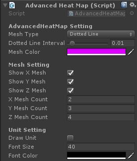
Inspector
其中的配置就比较简单了,具体细节见项目源码
网格光滑的问题
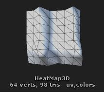
- 为什么示例图中的网格看起来棱角特别的分明,没有一个弧度的过度呢?
相信大家也明白在三维世界中的一切都是由三角面组成的,而且也没有正真绝对的弧线,而弧线都是由大量的短小的直线拼接出出来的,同样圆滑的弧面也是由大量的细分三角面来构成的,所以示例中的菱角特别分明是因为网格面数太低,实例中的网格面数应该只有64个三角面。
- 还有一点3dMax中的光滑组是什么意思呢?
加光滑组其实是将相邻的两个面的颜色值设置的更为接近,相邻面颜色越接近,那么弧面也将越显光滑,所以在温度图中顶点的颜色值计算也是较为重要的。
通过上述两个问题,我们应该清楚如何提升面的光滑程度,一,更多的三角面,二,面与面之间的颜色过度要合理。对应到我们的温度图组件中就是需要足够多的温度的点信息。
后续拓展
后续我们会将线条的绘制,网格的绘制进一步封装,同时与SpringGUI合并,封装出一个可绘制3D和2D图形的组件。
其实这个组件中还有较多的点需要去优化,比如每条线都会占用一个drawcall,我们需要将实例化的线条mesh合并,还有为了面的光滑,应该添加一个插入算法,让两个点之间通过贝塞尔或者别的算法有一个合理的过度。
UGUI组件系列
- Unity自定义UI组件(十二) 条形图篇
- Unity自定义UI组件(十一) 雷达图、属性图
- Unity自定义UI组件(十) 折线图
- Unity自定义UI组件(九) 颜色拾取器(下)
- Unity自定义UI组件(八) 颜色拾取器(上)
- Unity自定义UI组件(七)渐变工具、渐变色图片、渐变遮罩
- Unity自定义UI组件(六)日历、日期拾取器
- Unity自定义组件之(五) 目录树 UITree
- Unity自定义UI组件(四)双击按钮、长按按钮
- Unity自定义UI组件(三)饼图篇
- Unity自定义UI组件(二)函数图篇(下)
- Unity自定义UI组件(一)函数图篇(上)
Unity框架解读系列
- [Unity]PureMVC框架解读(下)
- [Unity]PureMVC框架解读(上)
分享地址(置顶目录包含所有组件的最新下载地址)
- Github :https://github.com/ll4080333/UnityCodes
- CSDN : http://blog.csdn.net/qq_29579137
- 博客专栏 : http://blog.csdn.net/column/details/16329.html
- 温度图组件下载地址 : http://download.csdn.net/download/qq_29579137/9968723
- QQ群 : 593906968 有什么不懂的可以加群咨询互相学习
如果你想了解UGUI的更多拓展组件,欢迎关注我的博客,我会持续更新,支持一下我这个博客新手,你的关注也会给予我更多的动力。如果以上文章对你有帮助,点个赞,让更多的人看到这篇文章,我们一起学习。如果有什么指点的地方欢迎在评论区留言,秒回复。


