FSM-based Digital Design 实例: 异步串行接收机
文章附图摘自《FSM-based Digitial Design Using Verilog HDL》
1. 系统框图
2. 状态转移图
3. FSM
// async receiver fsm
//
module async_rx_fsm (//input
st,en,rst,ack,ed,rxf,rxo,clk,
//output
PD,CDC,RXCK,DRY,ERR
);

input st; //start detection
input en; //enable the FSM
input rst;//reset signal
input ack; // feedback to data ready
input ed; // error detection input
input rxf; //div/11 counter can issue an full signal
input rxo; //unused
input clk; //fsm clock

output PD; // to pulse data latch
output CDC; // clear shift register and counter
output RXCK; //gating clock for counter and shift register
output DRY; //data ready signal
output ERR; //data error

parameter S0=4'b0000;
parameter S1=4'b1000;
parameter S2=4'b1100;
parameter S4=4'b1110;
parameter S5=4'b1111;
parameter S6=4'b1011;
parameter S7=4'b0011;
parameter S8=4'b0111;
parameter S9=4'b1101;
parameter S10=4'b0101;
parameter S11=4'b0110;
parameter S12=4'b0010;

reg [3:0] next_state;
reg [3:0] state;
always @(posedge clk or negedge rst) begin
		if (~rst)
				state <= 4'b0000;
		else
				state <= next_state;
end
always @(*) begin
		case (state)
			S0: begin
					if(en&~st)
							next_state = S1;
					else
							next_state = S0;
			end
			S1: begin
					next_state = S2;
			end
			S2: begin
					next_state = S4;
			end
			S4: begin
					next_state = S5;
			end
			S5: begin
					if(~rxf)
						next_state = S6;
					else
						next_state = S9;
			end
			S6: begin
					next_state = S7;
			end
			S7: begin
					next_state = S8;
			end
			S8: begin
					next_state = S5;
			end
			S9: begin
					if (ed)
						next_state = S11;
					else
						next_state = S10;
			end
			S11: begin
					if(ack)
						next_state = S12;
					else
						next_state = S11;
			end
			S12: begin
					if (~ack)
						next_state = S0;
					else
						next_state = S12;
			end
			default: begin
					next_state = S0;
			end

		endcase
end
assign RXCK = &state;
//0110
assign PD = (~state[3])&state[2]&state[1]&(~state[0]);
assign DRY = PD;
//0101
assign ERR = (~state[3])&state[2]&(~state[1])&state[0];
//
assign CDC = ~(~st&en&(~|state));
endmodule
module async_rx_fsm_top (
//input
clk,en,ack,data_in,rst,
//output
DRY,ERR,qout
);
input clk;
input en;
input ack;
input data_in;
input rst;
output DRY;
output ERR;
output [7:0] qout;
//wire
wire RXCK;
wire CDC;
wire PD;
wire QST;
wire [7:0] Q_reg;
wire QSP1;
wire QSP2;
wire [10:0] shift_q;

wire rxf;
wire ed;
async_rx_fsm inst_fsm(//input
.st(data_in),
.en(en),
.rst(rst),
.ack(ack), // from testbench
.ed(ed),
.rxf(rxf),
.rxo(), // unused
.clk(clk),
//output
.PD(PD),
.CDC(CDC),
.RXCK(RXCK),
.DRY(DRY), // to testbench
.ERR(ERR)); // to testbench

div11_cnt inst_div_11 (
.clr(CDC),
.clk(RXCK),
//output
.q(rxf));

shift_regs inst_shift_regs (
.clk(RXCK),
.clr(CDC),
.in(data_in),
//output
.q(shift_q));
//
assign QST =shift_q[10];
assign Q_reg = shift_q[9:2];
assign {QSP2,QSP1} = shift_q[1:0];

assign ed = ~QST&&QSP1&&QSP2;
data_latch inst_data_latch (
.clk(PD),
.d(Q_reg),
//output
.q(qout));

endmodule
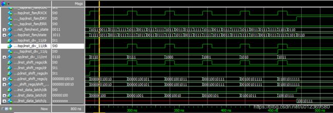
module tb();
reg clk;
reg rst;
reg st;
reg clk_in;
reg data_in;
reg en;
reg seed;
reg [7:0] wave;
wire clk_rxck;
		integer i;
		       assign  clk_rxck = u_async_rx_fsm_top.inst_fsm.RXCK;
initial begin
          clk = 0;
          clk_in = 0;

          rst = 0;
          data_in = 1;
          en = 0;
          seed =0;
          wave = 7'b0110101;
    #20  rst = 1;
    @(posedge clk_in) ;
     data_in = 0;
     en=1;
    //for (i=0;i<7;i=i+1) begin
    	@(posedge clk_rxck) data_in = 1;
    	@(posedge clk_rxck) data_in = 0;
    	@(posedge clk_rxck) data_in = 0;
    	@(posedge clk_rxck) data_in = 1;
    	@(posedge clk_rxck) data_in = 0;
    	@(posedge clk_rxck) data_in = 1;
    	@(posedge clk_rxck) data_in = 1;
    //end
    @(posedge clk_rxck) data_in = 1;
    @(posedge clk_rxck) data_in = 1;
    #2000 $finish;
end
always #5 clk =~clk;
always #20 clk_in = ~clk_in;
async_rx_fsm_top u_async_rx_fsm_top (
//input
.clk(clk),
.en(en),
.ack(),
.data_in(data_in),
.rst(rst),
//output
.DRY(),
.ERR(),
.qout());

endmodule


