STM32 串口实验
实验目的: 使用 STM32 的串口来发送和接收数据
实验步骤:
- STM32 串口简介
- 硬件设计
- 软件设计
- 下载验证
1. 串口简介
miniSTM32 板载 1 个USB串口和1个RS232串口,实验将使用USB串口将信息打印到电脑上;
串口设置步骤:
- 串口时钟使能,GPIO 时钟使能(使能函数)
RCC_APB2PeriphClockCmd(RCC_APB2Periph_USART1)
- 串口复位 (归初始化)
#define USART1 ((USART_TypeDef *) USART1_BASE)
void USART_DeInit(USART_TypeDef* USARTx);//串口复位,DeInit
USART_DeInit(USART1);  //复位串口 1;用的是串口1
- GPIO 端口模式设置 (设置为复用功能对应的模式)

- 串口参数初始化 (波特率,停止位等)
#define __IO volatile                  /*!< defines 'read / write' permissions   */
//volatile是一个类型修饰符(type specifier),就像我们熟悉的const一样,它是被设计用来修饰被不同线程访问和修改的变量;
//volatile的作用是作为指令关键字,确保本条指令不会因编译器的优化而省略,且要求每次直接读值;

void USART_Init(USART_TypeDef* USARTx, USART_InitTypeDef* USART_InitStruct);
typedef struct
{
  __IO uint16_t SR;
  uint16_t  RESERVED0;
  __IO uint16_t DR;
  uint16_t  RESERVED1;
  __IO uint16_t BRR;
  uint16_t  RESERVED2;
  __IO uint16_t CR1;
  uint16_t  RESERVED3;
  __IO uint16_t CR2;
  uint16_t  RESERVED4;
  __IO uint16_t CR3;
  uint16_t  RESERVED5;
  __IO uint16_t GTPR;
  uint16_t  RESERVED6;
} USART_TypeDef;
typedef struct
{
  uint32_t USART_BaudRate;            /*!< This member configures the USART communication baud rate.
                                           The baud rate is computed using the following formula:
                                            - IntegerDivider = ((PCLKx) / (16 * (USART_InitStruct->USART_BaudRate)))
                                            - FractionalDivider = ((IntegerDivider - ((u32) IntegerDivider)) * 16) + 0.5 */

  uint16_t USART_WordLength;          /*!< Specifies the number of data bits transmitted or received in a frame.
                                           This parameter can be a value of @ref USART_Word_Length */

  uint16_t USART_StopBits;            /*!< Specifies the number of stop bits transmitted.
                                           This parameter can be a value of @ref USART_Stop_Bits */

  uint16_t USART_Parity;              /*!< Specifies the parity mode.
                                           This parameter can be a value of @ref USART_Parity
                                           @note When parity is enabled, the computed parity is inserted
                                                 at the MSB position of the transmitted data (9th bit when
                                                 the word length is set to 9 data bits; 8th bit when the
                                                 word length is set to 8 data bits). */

  uint16_t USART_Mode;                /*!< Specifies wether the Receive or Transmit mode is enabled or disabled.
                                           This parameter can be a value of @ref USART_Mode */

  uint16_t USART_HardwareFlowControl; /*!< Specifies wether the hardware flow control mode is enabled
                                           or disabled.
                                           This parameter can be a value of @ref USART_Hardware_Flow_Control */
} USART_InitTypeDef;

//赋值
USART_InitStructure.USART_BaudRate = bound;         //波特率;
USART_InitStructure.USART_WordLength = USART_WordLength_8b;//字长为 8 位数据格式;
USART_InitStructure.USART_StopBits = USART_StopBits_1;        //一个停止位
USART_InitStructure.USART_Parity = USART_Parity_No;          //无奇偶校验位
USART_InitStructure.USART_HardwareFlowControl
                = USART_HardwareFlowControl_None;          //无硬件数据流控制
USART_InitStructure.USART_Mode = USART_Mode_Rx | USART_Mode_Tx; //收发模式
USART_Init(USART1, &USART_InitStructure);                   //初始化串口
- 开启中断并且初始化 NVIC(如果需要开启中断才需要这个步骤)
- 使能串口
- 编写中断处理函数
数据发送与接收
通过寄存器 USART_DR 来实现
typedef unsigned short int uint16_t;
void USART_SendData(USART_TypeDef* USARTx, uint16_t Data);	//发送数据函数;
uint16_t USART_ReceiveData(USART_TypeDef* USARTx);	//从串口读取数据;
函数的具体实现目前不需要了解,大致是通过位操作来保留和读取数据;
串口状态读取
根据对串口状态寄存器 USART_SR 中一些标志位的读取来判断数据是接收到还是发送出去;
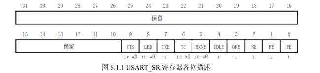
—RXNE(读数据寄存器非空),当该位被置 1 的时候,就是提示已经有数据被接收到了;
—TC(发送完成),当该位被置位的时候,表示 USART_DR 内的数据已经被发送完成了;
下面给出固件库函数里对状态读取的函数:
typedef enum {RESET = 0, SET = !RESET} FlagStatus, ITStatus;	//定义枚举,值为 0 or 1;
FlagStatus USART_GetFlagStatus(USART_TypeDef* USARTx, uint16_t USART_FLAG);
USART_GetFlagStatus(USART1, USART_FLAG_RXNE);	//判断读寄存器是否非空(RXNE);
USART_GetFlagStatus(USART1, USART_FLAG_TC);		//判断发送是否完成(TC);

//下面是这些标识符的宏定义,每一个都对应了 uint16_t 类型的一个值;
#define USART_FLAG_CTS                       ((uint16_t)0x0200)
#define USART_FLAG_LBD                       ((uint16_t)0x0100)
#define USART_FLAG_TXE                       ((uint16_t)0x0080)
#define USART_FLAG_TC                        ((uint16_t)0x0040)
#define USART_FLAG_RXNE                      ((uint16_t)0x0020)
#define USART_FLAG_IDLE                      ((uint16_t)0x0010)
#define USART_FLAG_ORE                       ((uint16_t)0x0008)
#define USART_FLAG_NE                        ((uint16_t)0x0004)
#define USART_FLAG_FE                        ((uint16_t)0x0002)
#define USART_FLAG_PE                        ((uint16_t)0x0001)
2. 硬件设计
跳线帽连接

3. 软件设计
//初始化 IO 串口 1
//bound:波特率
void uart_init(u32 bound)
{
	GPIO_InitTypeDef GPIO_InitStructure;
	USART_InitTypeDef USART_InitStructure;
	NVIC_InitTypeDef NVIC_InitStructure;

	//①串口时钟使能,GPIO 时钟使能,复用时钟使能
	RCC_APB2PeriphClockCmd(RCC_APB2Periph_USART1|
	RCC_APB2Periph_GPIOA, ENABLE);   //使能 USART1,GPIOA 时钟

	//②串口复位
	USART_DeInit(USART1);                                 //复位串口 1
	//③GPIO 端口模式设置,配置全双工的串口 1,那么 TX(PA9)管脚需要配置为推挽复用输出,RX(PA10)管脚配置为浮空输入或者带上拉输入
	GPIO_InitStructure.GPIO_Pin = GPIO_Pin_9;                  //ISART1_TX PA.9
	GPIO_InitStructure.GPIO_Speed = GPIO_Speed_50MHz;
	GPIO_InitStructure.GPIO_Mode = GPIO_Mode_AF_PP;       //复用推挽输出
	GPIO_Init(GPIOA, &GPIO_InitStructure);                     //初始化 GPIOA.9

	GPIO_InitStructure.GPIO_Pin = GPIO_Pin_10;                 //USART1_RX PA.10
	GPIO_InitStructure.GPIO_Mode = GPIO_Mode_IN_FLOATING;  //浮空输入
	GPIO_Init(GPIOA, &GPIO_InitStructure);                     //初始化 GPIOA.10

	//④串口参数初始化
	USART_InitStructure.USART_BaudRate = bound;               //波特率设置
	USART_InitStructure.USART_WordLength = USART_WordLength_8b; //字长为 8 位
	USART_InitStructure.USART_StopBits = USART_StopBits_1;        //一个停止位
	USART_InitStructure.USART_Parity = USART_Parity_No;           //无奇偶校验位
	USART_InitStructure.USART_HardwareFlowControl  = USART_HardwareFlowControl_None;     //无硬件数据流控制
	USART_InitStructure.USART_Mode = USART_Mode_Rx | USART_Mode_Tx;//收发模式
	USART_Init(USART1, &USART_InitStructure);                   //初始化串口
	#if EN_USART1_RX                                      //如果使能了接收

	//⑤初始化 NVIC
	NVIC_InitStructure.NVIC_IRQChannel = USART1_IRQn;
	NVIC_InitStructure.NVIC_IRQChannelPreemptionPriority=3 ;        //抢占优先级 3
	NVIC_InitStructure.NVIC_IRQChannelSubPriority = 3;          //子优先级 3
	NVIC_InitStructure.NVIC_IRQChannelCmd = ENABLE;      //IRQ 通道使能
	NVIC_Init(&NVIC_InitStructure);                             //中断优先级初始化

	//⑤开启中断
	USART_ITConfig(USART1, USART_IT_RXNE, ENABLE);         //开启中断
	#endif

	//⑥使能串口
	USART_Cmd(USART1, ENABLE);                             //使能串口
}
下面给出主函数:
int main(void)
 {
	u8 t;
	u8 len;
	u16 times=0;

	delay_init();	    	 //延时函数初始化
	NVIC_PriorityGroupConfig(NVIC_PriorityGroup_2);// 设置中断优先级分组2
	uart_init(9600);	 //串口初始化为9600
	LED_Init();		  	 //初始化与LED连接的硬件接口

	while(1)
	{
		if(USART_RX_STA&0x8000)		//发送信息
		{
			len=USART_RX_STA&0x3fff;//得到此次接收到的数据长度
			printf("\r\n您发送的消息为:\r\n");
			for(t=0;t<len;t++)
			{
				USART1->DR=USART_RX_BUF[t];
				while((USART1->SR&0X40)==0);//等待发送结束
			}
			printf("\r\n\r\n");//插入换行
			USART_RX_STA=0;
		}
		else	//接收信息;
		{
			times++;
			if(times%5000==0)
			{
				printf("\r\nALIENTEK MiniSTM32开发板 串口实验\r\n");
				printf("正点原子@ALIENTEK\r\n\r\n\r\n");
			}
			if(times%200==0)printf("请输入数据,以回车键结束\r\n");
			if(times%30==0)LED0=!LED0;//闪烁LED,提示系统正在运行.
			delay_ms(10);
		}
	}
}