keil5-2: 基于STM32F302RBT6的AD采样实验——单通道连续模式
今天调通了AD(ADC2,ADC_Channel_5),以下是完整代码。后续还要用DMA方式做一下AD。由于网上这个片子的资料少,所以我参考STM32F4的例程来写,但是二者还是有不一样的地方。
一 先记录一下还没解决的问题,希望有了解的小伙伴可以指导一下。
1 这款芯片中ADC voltage regulator 的作用?F1&F4中有无?
2 为什么设置了连续扫描模式就自动将DMAEN置1?
注:切勿将ADC通道 接到+5V,否则会损坏相应通道。
二 相应程序:(有些注释可能不太对)
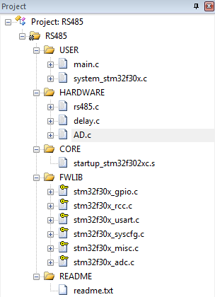
1 程序组成:
2、程序:
1 main.c
#include "delay.h"
#include "ad.h"
u8 rs485buf[5];
u8 len,key;
u8 RS485_RX_EN;
int main(void)
{
u8 i,t;
u8 cnt=0;
float adcx;
GPIO_InitTypeDef GPIO_InitStructure;
RCC_ClocksTypeDef ClockInfo;
NVIC_PriorityGroupConfig(NVIC_PriorityGroup_2);
RS485_Init(9600); //³õʼ»¯´®¿Ú²¨ÌØÂÊ9600
RCC_AHBPeriphClockCmd(RCC_AHBPeriph_GPIOB,ENABLE);
GPIO_InitStructure.GPIO_Pin = GPIO_Pin_0;
GPIO_InitStructure.GPIO_Mode = GPIO_Mode_OUT;
GPIO_InitStructure.GPIO_Speed = GPIO_Speed_2MHz;
GPIO_InitStructure.GPIO_OType = GPIO_OType_PP;
GPIO_InitStructure.GPIO_PuPd = GPIO_PuPd_NOPULL;
GPIO_Init(GPIOB,&GPIO_InitStructure);
adc_Init();
RCC_GetClocksFreq(&ClockInfo);
GPIO_SetBits(GPIOA,GPIO_Pin_12); //DEÖÃ1£¬485´¦ÓÚ·¢ËÍ״̬
printf("Äú½ÓÊÕµ½µÄÊý¾ÝΪ");
// GPIO_ResetBits(GPIOA,GPIO_Pin_12); //DEÇåÁ㣬485´¦ÓÚ½ÓÊÕ״̬
while(1) //Ñ»·µÈ´ý£¬
{
adcx = Get_Adc_Average(ADC_Channel_5,20);
printf("%f",adcx);
}
}
2 485.c&delay.c与头一篇文章是一样的
3 AD.c
#include "ad.h"
#include "delay.h"
#include "stm32f30x_adc.h"
void adc_Init(void)
{
GPIO_InitTypeDef GPIO_InitStructure;
ADC_CommonInitTypeDef ADC_CommonInitStructure;
ADC_InitTypeDef ADC_InitStructure;
RCC_ADCCLKConfig(RCC_ADC12PLLCLK_Div2); //ADC12CLK = PLLCLK/2
RCC_AHBPeriphClockCmd(RCC_AHBPeriph_ADC12|RCC_AHBPeriph_GPIOC,ENABLE); // 1 ¿ªÆôÏà¹ØʱÖÓ
GPIO_InitStructure.GPIO_Pin = GPIO_Pin_4; //²¢ÅäÖÃPC4:AD_V15V(ADC2_IN5)
GPIO_InitStructure.GPIO_Mode = GPIO_Mode_AN;
GPIO_InitStructure.GPIO_Speed = GPIO_Speed_50MHz;
GPIO_InitStructure.GPIO_PuPd = GPIO_PuPd_NOPULL;
GPIO_Init(GPIOC,&GPIO_InitStructure);
ADC_DeInit(A_D_C); // 2 ¸´Î»ADC2
ADC_CommonInitStructure.ADC_Mode = ADC_Mode_Independent; //¶ÀÁ¢Ä£Ê½
ADC_CommonInitStructure.ADC_DMAAccessMode = ADC_DMAAccessMode_Disabled; //²»ÓÃDMA
ADC_CommonInitStructure.ADC_TwoSamplingDelay = 5; //Á½¸ö²ÉÑù¼ä¸ô5¸öÖÜÆÚ
ADC_CommonInit(A_D_C,&ADC_CommonInitStructure); //ÅäÖÃADCµÄͨÓÃÌØÐÔ
ADC_InitStructure.ADC_Resolution = ADC_Resolution_12b; //12λ
ADC_InitStructure.ADC_ContinuousConvMode = ENABLE; //ʹÄÜÁ¬Ðøת»»
ADC_InitStructure.ADC_ExternalTrigEventEdge = ADC_ExternalTrigEventEdge_None; //ÎÞÍⲿ´¥·¢Ê¼þ
ADC_InitStructure.ADC_OverrunMode = DISABLE;
ADC_InitStructure.ADC_AutoInjMode = DISABLE;
ADC_InitStructure.ADC_DataAlign = ADC_DataAlign_Right; //ÓÒ¶ÔÆë
ADC_InitStructure.ADC_NbrOfRegChannel = 1; //ÐèҪת»»µÄͨµÀÊý
ADC_Init(A_D_C,&ADC_InitStructure); //ÅäÖþßÌåµÄADCÌØÐÔ
A_D_C->CR &=0x0FFFFFFF;
A_D_C->CR |=0x10000000; //¿ªÆôADC regulator
delay(50000); //ÑÓʱ£¬ÒÔʹregulator ÓÐ×ã¹»µÄʱ¼äÍê³ÉÆô¶¯
ADC_Cmd(A_D_C,ENABLE);
// ADCµÄÒ»´Îת»»Ê±¼äTconv=1/35M *(1.5+12)=0.386us
}
//»ñµÃADCÖµ
//ch: @ref ADC_channels
//ͨµÀÖµ 0~16È¡Öµ·¶Î§Îª£ºADC_Channel_0~ADC_Channel_16
//·µ»ØÖµ:ת»»½á¹û
u16 Get_Adc(u8 ch)
{
//ÉèÖÃÖ¸¶¨ADCµÄ¹æÔò×éͨµÀ£¬Ò»¸öÐòÁУ¬²ÉÑùʱ¼ä
ADC_RegularChannelConfig(A_D_C,ch,1,ADC_SampleTime_181Cycles5); //ÅäÖÃADCµÄ²ÉÑùʱ¼äΪ181.5¸öÖÜÆÚ
// ADC_RegularChannelConfig(ADC1, ADC_Channel_1|ADC_Channel_6|ADC_Channel_7|ADC_Channel_8, 1, ADC_SampleTime_601Cycles5 ); //ADC1,ADCͨµÀ,480¸öÖÜÆÚ,Ìá¸ß²ÉÑùʱ¼ä¿ÉÒÔÌá¸ß¾«È·¶È
// ADC_RegularChannelConfig(ADC2, ADC_Channel_1|ADC_Channel_2|ADC_Channel_3|ADC_Channel_4|ADC_Channel_5, 1, ADC_SampleTime_601Cycles5 );
ADC_StartConversion(A_D_C); //ʹÄÜÖ¸¶¨µÄADC1µÄÈí¼þת»»Æô¶¯¹¦ÄÜ
ADC_GetStartConversionStatus(A_D_C);
while(ADC_GetFlagStatus(A_D_C, ADC_FLAG_EOC ) == RESET);//µÈ´ýת»»½áÊø
return ADC_GetConversionValue(A_D_C); //·µ»Ø×î½üÒ»´ÎADC1¹æÔò×éµÄת»»½á¹û
}
//»ñȡͨµÀchµÄת»»Öµ£¬È¡times´Î,È»ºóƽ¾ù
//ch:ͨµÀ±àºÅ
//times:»ñÈ¡´ÎÊý
//·µ»ØÖµ:ͨµÀchµÄtimes´Îת»»½á¹ûƽ¾ùÖµ
u16 Get_Adc_Average(u8 ch,u8 times)
{
u32 temp_val=0;
u8 t;
for(t=0;t
temp_val+=Get_Adc(ch);
delay(500000);
}
return temp_val/times;
}
4 ad.h
#ifndef __AD_H
#define __AD_H
#include "stm32f30x_gpio.h"
#include "stm32f30x_rcc.h"
#include "stm32f30x_adc.h"
#include "stm32f30x.h"
void adc_Init(void);
u16 Get_Adc(u8 ch);
u16 Get_Adc_Average(u8 ch,u8 times);
#define A_D_C ADC2
#endif
