边界扫描和JTAG端口
边界扫描:通过在ASIC的I/O引脚插入边界扫描单元(Boundary Scan cells),并在芯片周围将他们连接成移位寄存器,从而将扫描链路加入网表中。

两个多路选择器控制了单元的数据通路:
正常模式:(1)当mode为0时,单元处于正常模式,data_in通过多路选择器传输到data_out,扫描链不影响ASIC工作
JTAG操作模式:
(1)扫描:当shiftDR为1,数据在clockDR的有效沿通过scan_in,并通过data_out输出
(2)捕获:当shiftDR为1,在clockDR的有效沿,数据波载入捕获寄存器
(3)更新:当mode为1,在updateDR的有效沿捕获寄存器的输出被移入更新寄存器
module BSC_Cell(
input data_in,
input scan_in,
input shiftDR,
input mode,
input clockDR,
input updateDR,
output data_out,
output reg scan_out);
reg update_reg;
always@(posedge clockDR)
begin
	scan_out<=shiftDR?scan_in:data_in;
end
always@(posedge updateDR)
begin
	updateDR<=scan_out;
end
assign data_out=mode?updateDR:data_in;
endmodule
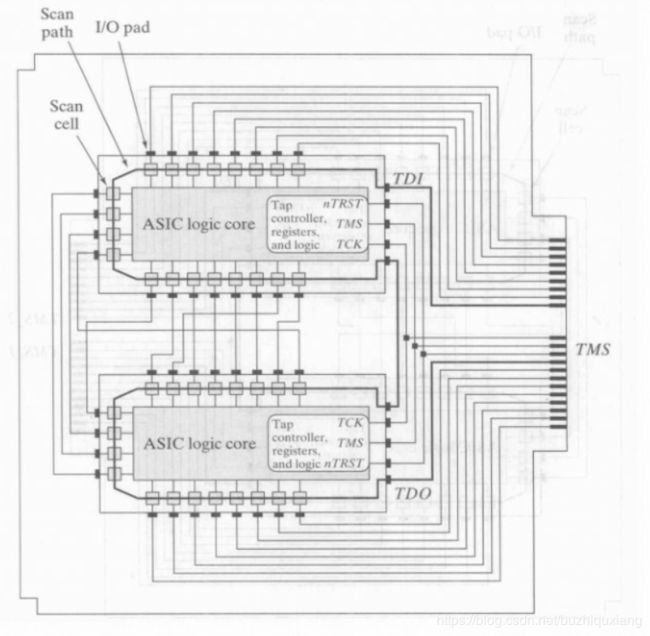
边界扫描方法可以测试PC板上的多片芯片、芯片间的板上布线、芯片引脚和核心逻辑之间的连接等(测试器可以将内嵌有边界扫描电路和专用测试存取端口(TAP,JTAG端口)的ASIC核心逻辑模块分离出来,并加以测试)
JTAG端口除了可以测试ASIC和印制电路板的制造缺陷之外,可用来对可配置的PLD和FPGA器件编程,还可以通过控制处理器和访问内部寄存器,对嵌入式处理器的软件进行开发和调试。
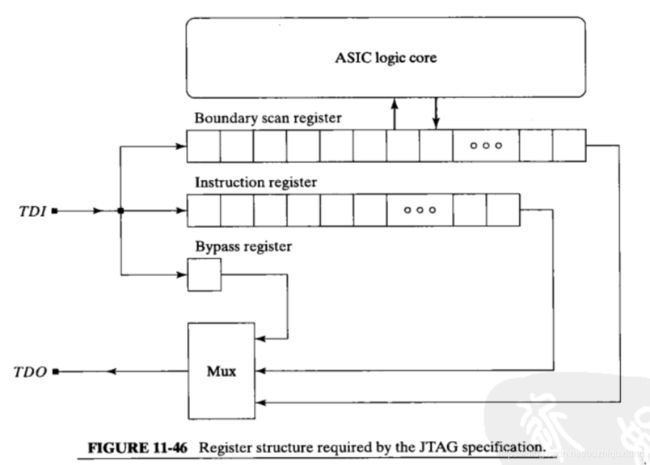
应用JTAG方法的芯片包括边界扫描寄存器、旁路寄存器和指令寄存器

module BR_Cell(
input scan_in,
input shiftDR,
input clockDR,
output reg scan_out);
always@(posedge clockDR)
begin
	scan_out<=scan_in&shiftDR;
end
endmodule
- 指令寄存器:指令寄存器的当前指令决定了哪个寄存器是连接在测试数据输入TDI与测试数据输出TDO之间(实际的寄存器可以由内部扫描链路上的一个或多个测试数据寄存器TDR连接而成)
指令寄存器指定了TAP内部指令和控制TAP的数据通路,且具有异步置位/复位功能

module IR_cell(
input shiftIR,
input data_in,
input scan_in,
input clockIR,
input updateIR,
input reset_bar,
input nTRST,
output reg scan_out,
output reg data_out);
wire S_R=reset_bar&nTRST;
always@(posedge clockIR)
begin
	scan_out<=shiftIR?scan_in:data_in;
end
always@(posedge updateIR or negedge S_R)
begin
	if(!S_R)
		data_out<=0;
	else
		data_out<=scan_out;
end
endmodule
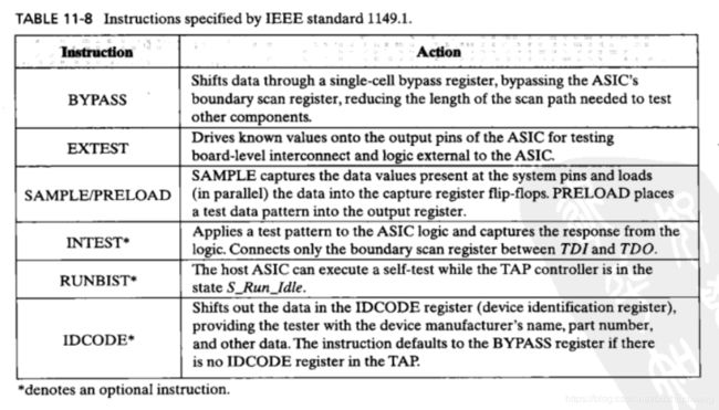
JTAG指令:

TAP结构(TDI,TMS和nTRST输入端口均有上拉电路)

TAP的TDI和TDO引脚分别连接到边界扫描寄存器链路中的第一个和最后一个单元,作为芯片的接口(TDI作为输入将测试模板以串行方式施加于端口,TDO作为串行输出端口
TAP的工作模式可通过TMS的输入端来控制,控制TAP控制器的状态转移,每一次转移都在TCLK的上升沿,由TAP控制器产生的信号驱动寄存器单元的输入shiftDR,mode,clockDR,updateDR,shiftDR,clockIR和updateIR
测试用的主时钟信号应加到测试时钟TCK的输入引脚

