【OpenCV&OpenGL&Marker-based AR】原理部分
文章目录
- 说在前面
- 针孔相机模型
- 原理
- OpenCV Part
- 相机标定
- 相机内参(Camera Parameter)
- 畸变系数(Distortion coeffs)
- 相机外参
- OpenGL Part
- Model Matrix
- View Matrix
- Projection Matrix
- 注意事项
- OpenCV&OpenGL(重点)
- 具体流程
说在前面
- opencv版本:4.0.1
- opencv aruco版本:4.0.1
- opengl:使用glad、glfw
- ar实现:基于标记(marker)
- 其他说明:在AR学习中的一些理解,尽量使用图画来说明;
- 代码部分:【OpenCV&OpenGL&Marker-based AR】代码部分-带纹理方块
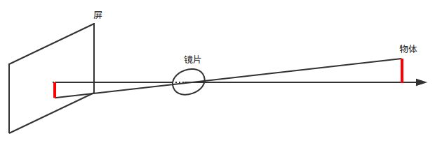
针孔相机模型
- 记得中学的凸透镜实验吗?
-
原理
我们将镜头后面那个屏移动到镜头前面来(下面是三维图):

由三角形相似(关注蓝色、红色、绿色部分)可以得到:
{ x c x = z c f y c y = z c f \left\{ \begin{gathered} \frac{x_c} {x} = \frac{z_c}{f} \\ \frac{y_c} {y} = \frac{z_c}{f} \end{gathered} \right. ⎩⎪⎨⎪⎧xxc=fzcyyc=fzc
即:
{ x = x c ∗ f z c y = y c ∗ f z c \left\{ \begin{gathered} x = \frac{x_c*f}{z_c} \\ y = \frac{y_c*f}{z_c} \end{gathered} \right. ⎩⎪⎪⎨⎪⎪⎧x=zcxc∗fy=zcyc∗f
换化成矩阵形式:
z c [ x y 1 ] = [ f 0 0 0 f 0 0 0 1 ] [ x c y c z c ] z_c\left[ \begin{matrix} x \\ y \\ 1 \end{matrix} \right]= \left[ \begin{matrix} f & 0 & 0 \\ 0& f & 0 \\ 0& 0&1 \end{matrix} \right] \left[ \begin{matrix} x_c \\ y_c \\ z_c \end{matrix} \right] zc⎣⎡xy1⎦⎤=⎣⎡f000f0001⎦⎤⎣⎡xcyczc⎦⎤
假设相机中心对应的坐标为 x 0 x_0 x0、 y 0 y_0 y0(上述的公式是以相机中心为坐标系原点进行计算的,现在我们将坐标系原点移动到感光元件左上角),那么就有:
{ x = x c ∗ f z c + x 0 y = y c ∗ f z c + y 0 \left\{ \begin{gathered} x = \frac{x_c*f}{z_c} + x_0 \\ y = \frac{y_c*f}{z_c} + y_0 \end{gathered} \right. ⎩⎪⎪⎨⎪⎪⎧x=zcxc∗f+x0y=zcyc∗f+y0
换化成矩阵形式:
z c [ x y 1 ] = [ f 0 x 0 0 f y 0 0 0 1 ] [ x c y c z c ] z_c\left[ \begin{matrix} x \\ y \\ 1 \end{matrix} \right]= \left[ \begin{matrix} f & 0 & x_0 \\ 0& f & y_0 \\ 0& 0&1 \end{matrix} \right] \left[ \begin{matrix} x_c \\ y_c \\ z_c \end{matrix} \right] zc⎣⎡xy1⎦⎤=⎣⎡f000f0x0y01⎦⎤⎣⎡xcyczc⎦⎤
OpenCV Part
-
相机标定
通过相机标定来确定真实相机的参数(内参)以及畸变系数,主要使用opencv aruco模块,可参考官方教程或者demo
-
相机内参(Camera Parameter)
在OpenCV中,相机内参是一个3x3的矩阵;其形式为
[ f x 0 c x 0 f y c y 0 0 1 ] \left[ \begin{matrix} f_x & 0 & c_x \\ 0 & f_y& c_y\\ 0 & 0 &1\\ \end{matrix} \right] ⎣⎡fx000fy0cxcy1⎦⎤
其中 f x f_x fx、 f y f_y fy为尺度因子, c x c_x cx、 c y c_y cy为相机中心的坐标; f x f_x fx、 f y f_y fy与焦距 f f f不相等,而是下述的关系:
{ f x = f d x f y = f d y \left\{ \begin{gathered} f_x=\frac{f}{dx}\\ f_y=\frac{f}{dy} \end{gathered} \right. ⎩⎪⎪⎨⎪⎪⎧fx=dxffy=dyf
其中 d x dx dx、 d y dy dy为感光元件中像素的大小(宽、高);推导:在针孔相机模型中我们只是将实际物体投影到感光元件中,现在我们需要将感光元件中的图像转化为我们熟悉的电子图像。我们假设电子图像中像素宽高均为单位1,那么:

{ u = x d x ∗ 1 v = y d y ∗ 1 \left\{ \begin{gathered} u=\frac{x}{dx}*1\\ v=\frac{y}{dy}*1 \end{gathered} \right. ⎩⎪⎨⎪⎧u=dxx∗1v=dyy∗1
换化成矩阵形式(由于都是二维,没有z分量):
[ u v 1 ] = [ 1 / d x 0 0 0 1 / d y 0 0 0 1 ] [ x y 1 ] \left[ \begin{matrix} u \\ v \\ 1 \end{matrix} \right]= \left[ \begin{matrix} 1/dx & 0 & 0 \\ 0& 1/dy & 0 \\ 0& 0&1 \end{matrix} \right] \left[ \begin{matrix} x \\ y \\ 1 \end{matrix} \right] ⎣⎡uv1⎦⎤=⎣⎡1/dx0001/dy0001⎦⎤⎣⎡xy1⎦⎤
合并一下(即从实际物体直接到电子图像,简单的矩阵乘法)就有:
[ 1 / d x 0 0 0 1 / d y 0 0 0 1 ] [ f 0 x 0 0 f y 0 0 0 1 ] = [ f / d x 0 x 0 / d x 0 f / d y y 0 / d y 0 0 1 ] \left[ \begin{matrix} 1/dx & 0 & 0 \\ 0& 1/dy & 0 \\ 0& 0&1 \end{matrix} \right] \left[ \begin{matrix} f & 0 & x_0 \\ 0& f & y_0 \\ 0& 0&1 \end{matrix} \right]= \left[ \begin{matrix} f/dx & 0 & x_0/dx \\ 0& f/dy & y_0/dy \\ 0& 0&1 \end{matrix} \right] ⎣⎡1/dx0001/dy0001⎦⎤⎣⎡f000f0x0y01⎦⎤=⎣⎡f/dx000f/dy0x0/dxy0/dy1⎦⎤相机参数栗子 (
我使用的相机[640x480]的内参):
840.263 0.0 317.134 0.0 836.454 197.918 0.0 0.0 1.0 \begin{matrix} 840.263 & 0.0 & 317.134 \\ 0.0 & 836.454 & 197.918 \\ 0.0 & 0.0 & 1.0 \\ \end{matrix} 840.2630.00.00.0836.4540.0317.134197.9181.0 -
畸变系数(Distortion coeffs)
由于光线在穿过镜头的时候会发生一定的畸变,因此需要通过畸变系数进行校正;这部分暂不关注。
-
相机外参
通过相机外参可以得到相机在世界坐标系中的位置以及镜头的朝向;在OpenCV aruco中可以使用以下函数
void cv::aruco::estimatePoseSingleMarkers( InputArrayOfArrays corners, //函数detectMarkers()检测到的标记角的坐标集合 float markerLength, //标记长度 InputArray cameraMatrix, //相机内参矩阵 InputArray distCoeffs, //畸变系数矩阵 OutputArray rvecs, //输出,旋转向量 OutputArray tvecs //输出,平移向量 );一般使用Vec3d作为单个旋转向量以及平移向量的类型,即(x,y,z);通过旋转向量改变相机的朝向,平移向量改变相机在世界坐标系中的位置。
- 举个栗子,假设rvec=(-1, -1, -1), tvec=(1, 1, 1);
- 假定相机初始状态为:放置在世界坐标系原点,镜头朝向Z轴正方向(OpenGL中朝Z负方向);
- 根据旋转向量rvec=(-1, -1, -1)进行旋转,其具体意义为绕向量(-1, -1, -1)旋转弧度为|rvec|(rvec的模)
- 将相机中心沿向量tvec的方向移动|tvec|(tvec的模)长度
OpenGL Part
-
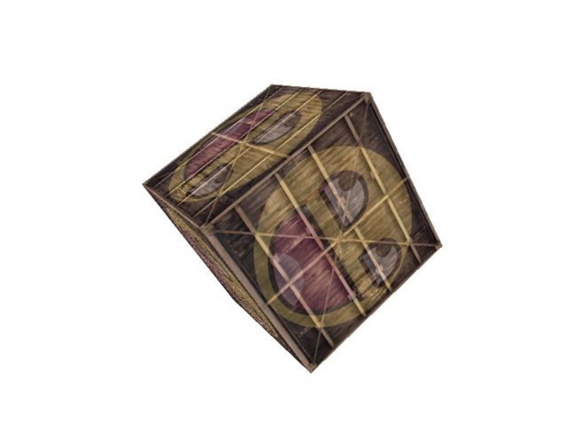
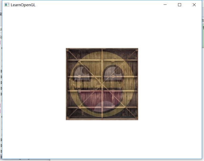
这部分可以参考LearnOpenGL教程,这里就使用一个栗子来说明吧!我们首先在OpenGL中创建一个立方体,如下图(用的是LearnOpenGL中那个,下图进行了旋转,栗子中我们使用正常的角度)
-
Model Matrix
【相当于调整模型在世界坐标系中的位置】
初始状态,正方体边长为1.0f,中心在原点;相机也在原点,朝向Z负半轴
(注意:前两个实验中我们设置了Projection Matrix,便于观察实验结果。)
若不改变Model Matrix,看到的图像为(如上图,相机在立方体内部):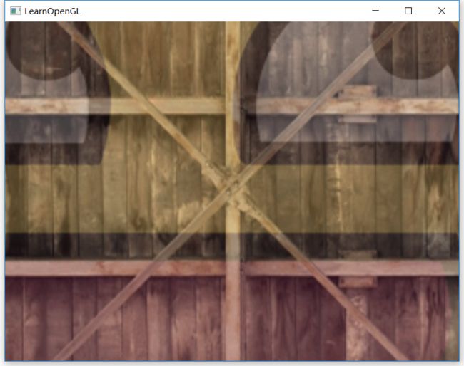
若使用Model Matrix将立方体往Z负半轴移动,则(下图分别为移动2、3距离,此时相机在立方体外):
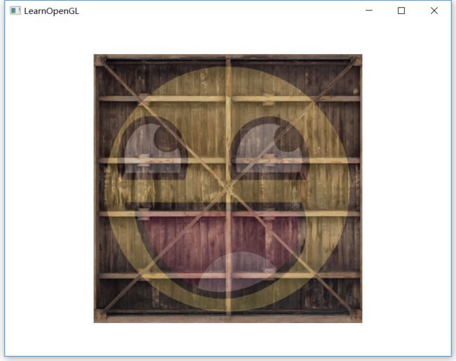
可以看到越来越小 -
View Matrix
【相当于相机外参】
现在我们不改变Model Matrix(立方体中心还是在世界坐标系原点),移动相机(使用lookAt函数);
若将相机沿Z负半轴移动到立方体外(不改变朝向),我们应该看不到立方体,如下图:
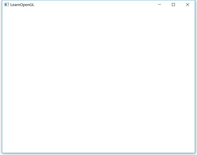
若沿正半轴移动到立方体外(不改变朝向),则:

-
Projection Matrix
【相当于相机内参】
这部分看教程吧,讲的比较清楚 -
注意事项
在OpenGL中矩阵是以列为主元素,与OpenCV相反,要注意转换;例如,
OpenCV中:
[ f / d x 0 x 0 / d x 0 f / d y y 0 / d y 0 0 1 ] \left[ \begin{matrix} f/dx & 0 & x_0/dx \\ 0& f/dy & y_0/dy \\ 0& 0&1 \end{matrix} \right] ⎣⎡f/dx000f/dy0x0/dxy0/dy1⎦⎤
则OpenGL中:
[ f / d x 0 0 0 f / d y 0 x 0 / d x y 0 / d y 1 ] \left[ \begin{matrix} f/dx & 0 & 0\\ 0& f/dy & 0 \\ x_0/dx& y_0/dy&1 \end{matrix} \right] ⎣⎡f/dx0x0/dx0f/dyy0/dy001⎦⎤
OpenCV&OpenGL(重点)
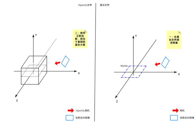
- 现在我们开始最重要的部分,我所理解的AR的过程;
- 首先我们有两个摄像头,一个OpenGL中使用的相机,另一个真实的相机
- 然后,我们有两个世界坐标系(
应该吧?),一个OpenGL的,一个OpenCV的(或者真实世界中的) - 我们要做的就是用OpenGL中的相机模拟实际使用的相机(从内参、外参上),同时要将两个世界坐标系重合,这样OpenGL中的物体就可以渲染到我们指定的位置
-
具体流程
- 使用OpenCV获取真实相机的位置(即rvec&tvec)
这部分使用标记Marker来实现,也就是OpenCV中aruco模块;我们假定Marker的中心为世界坐标系原点,并建立坐标系;真实相机的位置指的就是在该坐标系中的位置
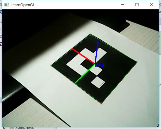
图-OpenCV捕获 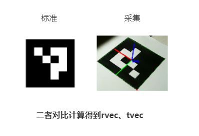
-
通过rvec、tvec计算View Matrix,从而移动OpenGL相机
View Matrix的形式为:
[ R t 0 1 ] \left[ \begin{matrix} R & t \\ 0 & 1 \end{matrix} \right] [R0t1]
其中R为3x3的旋转矩阵,t为3x1的平移矩阵;View Matrix为4x4矩阵。
旋转矩阵R可通过OpenCV函数**Rodrigues()**获得Rodrigues( InputArray src,//输入,可为1x3或者3x1向量,也可为3x3的矩阵 OutputArray res//输出,为对应的3x3旋转矩阵,或者旋转向量 ) //在该项目中,我们可这样调用 cv::Mat rot; Rodrigues(rvec, rot);//rvec为3x1旋转向量这样,View Matrix的形式就是:
[ r 00 r 01 r 02 t 0 r 10 r 11 r 12 t 1 r 20 r 21 r 22 t 2 0 0 0 1 ] \left[ \begin{matrix} r_{00} &r_{01}&r_{02} & t_0 \\ r_{10} &r_{11}&r_{12} & t_1 \\ r_{20} &r_{21}&r_{22} & t_2 \\ 0 &0&0& 1 \end{matrix} \right] ⎣⎢⎢⎡r00r10r200r01r11r210r02r12r220t0t1t21⎦⎥⎥⎤
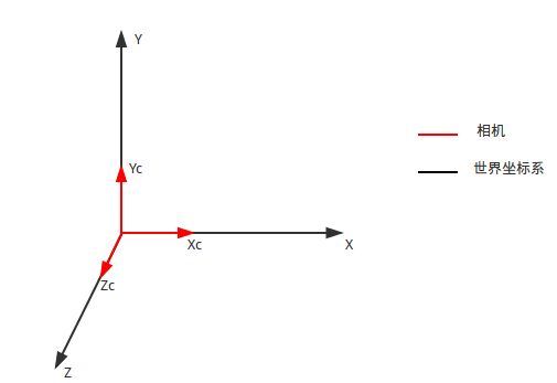
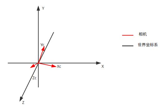
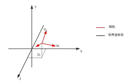
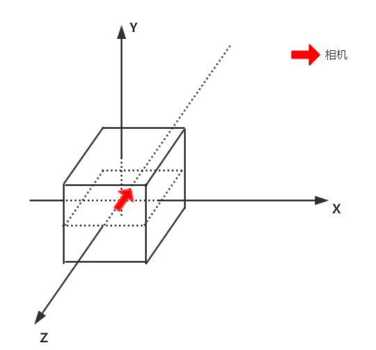
但是注意,上述所有数据都是在OpenCV的坐标系中计算得到的,我们现在需要将其转换为OpenGL坐标系;如下图,两个坐标系X轴方向相同,Y、Z轴相反,所以我们只需要将Y、Z轴反向即可。
 具体为与一个矩阵相乘:
[ 1 0 0 0 0 − 1 0 0 0 0 − 1 0 0 0 0 1 ] ∗ [ r 00 r 01 r 02 t 0 r 10 r 11 r 12 t 1 r 20 r 21 r 22 t 2 0 0 0 1 ] \left[ \begin{matrix} 1&0&0&0 \\ 0&-1&0&0 \\ 0&0&-1&0 \\ 0&0&0& 1 \end{matrix} \right]* \left[ \begin{matrix} r_{00} &r_{01}&r_{02} & t_0 \\ r_{10} &r_{11}&r_{12} & t_1 \\ r_{20} &r_{21}&r_{22} & t_2 \\ 0 &0&0& 1 \end{matrix} \right] ⎣⎢⎢⎡10000−10000−100001⎦⎥⎥⎤∗⎣⎢⎢⎡r00r10r200r01r11r210r02r12r220t0t1t21⎦⎥⎥⎤ -
将OpenCV获取的图像正射投影到OpenGL相机
【图 OpenCV捕获】就是OpenCV捕捉的图像;由于在该项目中我们以OpenGL为主,OpenCV为辅,所以我们需要将OpenCV的图像搞到OpenGL的相机中。使用正射投影:OpenCV捕获的图像已经是我们实际生成的电子图像了(即从真实世界→感光元件→电子图像),在OpenGL的相机中,我们就不需要再进行各种变换,相当于直接复制到OpenGL的最终图像,这份图像就是背景图啦
(下图说明:假设坐标系已经调整成一致的)
-
根据真实相机的内参构造Projection Matrix
最后我们需要调整OpenGL相机的参数,让其与真实使用的相机参数一致,这样OpenGL世界中的物体就可以映射到正确的位置。

- 首先拿出我们的Camera Matrix以及相机分辨率(即生成的图像大小,我的是640*480)
[ f x 0 c x 0 f y c y 0 0 1 ] \left[ \begin{matrix} f_x & 0 & c_x \\ 0 & f_y& c_y\\ 0 & 0 &1\\ \end{matrix} \right] ⎣⎡fx000fy0cxcy1⎦⎤ - 然后计算,这部分参考这篇文章,这里记录下推导过程
假设Projection Matrix为
[ a 0 0 0 0 b 0 0 0 0 A B 0 0 − 1 0 ] \left[ \begin{matrix} a & 0 & 0 & 0\\ 0& b & 0 & 0\\ 0& 0 & A & B\\ 0& 0 & -1& 0 \end{matrix} \right] ⎣⎢⎢⎡a0000b0000A−100B0⎦⎥⎥⎤
对于OpenGL世界中的某一点(X,Y,Z)有
[ a 0 0 0 0 b 0 0 0 0 A B 0 0 − 1 0 ] ∗ [ X Y Z 1 ] = [ a X b Y A Z + B − Z ] \left[ \begin{matrix} a & 0 & 0 & 0\\ 0& b & 0 & 0\\ 0& 0 & A & B\\ 0& 0 & -1& 0 \end{matrix} \right]* \left[ \begin{matrix} X\\ Y\\ Z\\ 1 \end{matrix} \right]= \left[ \begin{matrix} aX\\ bY\\ AZ+B\\ -Z \end{matrix} \right] ⎣⎢⎢⎡a0000b0000A−100B0⎦⎥⎥⎤∗⎣⎢⎢⎡XYZ1⎦⎥⎥⎤=⎣⎢⎢⎡aXbYAZ+B−Z⎦⎥⎥⎤
由于OpenGL会对其进行剪裁,即
( a X − Z , b Y − Z , A Z + B − Z ) (\frac{aX}{-Z}, \frac{bY}{-Z}, \frac{AZ+B}{-Z}) (−ZaX,−ZbY,−ZAZ+B)
并且三个分量均须处于[-1,1]内,即
{ − 1 ≤ a X − Z ≤ 1 − 1 ≤ b Y − Z ≤ 1 − 1 ≤ A Z + B − Z ≤ 1 \left\{ \begin{gathered} -1\le\frac{aX}{-Z}\le1\\ -1\le\frac{bY}{-Z}\le1\\ -1\le\frac{AZ+B}{-Z}\le1 \end{gathered} \right. ⎩⎪⎪⎪⎪⎪⎪⎨⎪⎪⎪⎪⎪⎪⎧−1≤−ZaX≤1−1≤−ZbY≤1−1≤−ZAZ+B≤1
由针孔相机模型中的三角形相似有
{ X Z = x f Y Z = y f \left\{ \begin{gathered} \frac{X} {Z} = \frac{x}{f} \\ \frac{Y} {Z} = \frac{y}{f} \end{gathered} \right. ⎩⎪⎪⎨⎪⎪⎧ZX=fxZY=fy
这个是到感光元件的转换,到电子图像为(我们可以将fx看作f在x方向的焦距)
{ X Z = x f x Y Z = y f y \left\{ \begin{gathered} \frac{X} {Z} = \frac{x}{f_x} \\ \frac{Y} {Z} = \frac{y}{f_y} \end{gathered} \right. ⎩⎪⎪⎨⎪⎪⎧ZX=fxxZY=fyy
所以
{ − 1 ≤ a x f x ≤ 1 − 1 ≤ b y f y ≤ 1 \left\{ \begin{gathered} -1\le\frac{ax}{f_x}\le1\\ -1\le\frac{by}{f_y}\le1 \end{gathered} \right. ⎩⎪⎪⎨⎪⎪⎧−1≤fxax≤1−1≤fyby≤1
我们假设坐标原点在图像中心,那么x取值范围为[-w/2,w/2],y取值范围为[-h/2,h/2];代入可得
{ a = 2 f x w b = 2 f y h \left\{ \begin{gathered} a=\frac{2f_x}{w}\\ b=\frac{2f_y}{h} \end{gathered} \right. ⎩⎪⎪⎨⎪⎪⎧a=w2fxb=h2fy
但是我们的坐标原点并不在图像中心,改变Projection Matrix
[ 2 f x w 0 c 0 0 2 f y h d 0 0 0 A B 0 0 − 1 0 ] \left[ \begin{matrix} \frac{2f_x}{w} & 0 & c& 0\\ 0& \frac{2f_y}{h} & d & 0\\ 0& 0 & A & B\\ 0& 0 & -1& 0 \end{matrix} \right] ⎣⎢⎢⎡w2fx0000h2fy00cdA−100B0⎦⎥⎥⎤
也就是
( a X − Z − c , b Y − Z − d , A Z + B − Z ) (\frac{aX}{-Z}-c, \frac{bY}{-Z}-d, \frac{AZ+B}{-Z}) (−ZaX−c,−ZbY−d,−ZAZ+B)
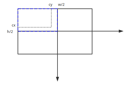
我们从另一个角度理解,就是移动坐标原点,两点分别为(0,0)、(-w/2+cx,h/2-cy),移动距离为
w / 2 − c x , − h / 2 + c y w/2-c_x, -h/2+c_y w/2−cx,−h/2+cy
这是在图像上的距离,转换为[-1, 1]中的距离,即除以w/2、h/2,为
1 − 2 c x / w , − 1 + 2 c y / h 1-2c_x/w, -1+2c_y/h 1−2cx/w,−1+2cy/h
A、B的推导这里就不记录了 - 最后的形式长这个亚子
[ 2 f x w 0 1 − 2 c x w 0 0 2 f y h 2 c y h − 1 0 0 0 − f + n f − n − 2 f n f − n 0 0 − 1 0 ] \left[ \begin{matrix} \frac{2f_x}{w} & 0 & 1-\frac{2c_x}{w} &0 \\ 0 & \frac{2f_y}{h}& \frac{2c_y}{h}-1 & 0\\ 0 & 0 &-\frac{f+n}{f-n}&-\frac{2fn}{f-n}\\ 0 & 0 & -1&0 \end{matrix} \right] ⎣⎢⎢⎡w2fx0000h2fy001−w2cxh2cy−1−f−nf+n−100−f−n2fn0⎦⎥⎥⎤
- 使用OpenCV获取真实相机的位置(即rvec&tvec)
END-(CSDN)
代码下一篇讲@_@