pci总线扫描设备本地操作(二)(local bus operation)
当type1命令通过桥片转换为type0命令格式或者是type0命令在到达总线后,是怎么查找到设备的呢?
接下来就看一下这个过程的操作。
type0命令只是在本地总线进行操作,不会传递到其他总线上,如果要查找的设备在其他总线上,那就会被master-abort终止。
type1命令会在不同的总线上进行传播,直到找到对应设备所在桥片后转换为type0格式,并且除了pci桥其他设备不会对type1进行响应。
下面格式适合域PC_AT(x86架构)兼容模式,其他架构类似
一,软件产生配置命令(software generation of configuration transaction)
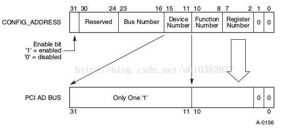
在x86上有两个寄存器 address(CF8)寄存器,data(CFC)寄存器。当要访问一个读设备的寄存器时,首先把要读取的设备的地址和要读取哪个寄存器写入到address中,之后在读取data寄存器获取读取的值;写操作类似,就把把data中的值写入到寄存器中。
那这个address寄存器要写入什么值?
如图:
31位决定data寄存器是否使能。
这就是基本的配置信息
之后这个address中的值会转换为AD(地址线)上的值,然后选中设备。
如图:
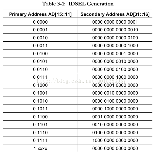
device number产生地址的对应关系,会在IDSEL说明。
二,软件产生special cycle(software generation of special cycle)
When the CONFIG_ADDRESS register is written with a value such that the Bus Number matches the bridge's bus number, the Device Number
is all 1's, the Function Number is all 1's, and the Register Number has a value of zero, then the bridge is primed to generate a
transaction using a Special Cycle command the next time the CONFIG_DATA register is written. When the CONFIG_DATA register is written
, the bridge generates a transaction that uses a Special Cycle command encoding (rather than Configuration Write command) on the
C/BE[3::0]# pins during the address phase and drives the data from the I/O write onto AD[31::00] during the first data phase. After
CONFIG_ADDRESS has been set up this way, reads to CONFIG_DATA have undefined results. In one possible implementation,the bridge can
treat it as a normal configuration operation (i.e., generate a Type 0 configuration transaction on the PCI bus). This will terminate
with a Master-Abort and the processor will have all 1's returned.If the Bus Number field of CONFIG_ADDRESS does not match the
bridge's bus number,then the bridge passes the write to CONFIG_DATA on through to PCI as a Type 1 configuration transaction just like
any other time the bus numbers do not match.
三,选择设备的配置空间(selection of device's configuration space)
1,单功能设备
当这个设备时单功能时,总线的操作:
1)配置命令解析(type1命令被桥解析位type0,只有type0命令才能配置总线上设备)
2)设备的IDSEL置位
3)AD[1:0]为0
设备使DEVSEL位使能,声明这次的配置。否则忽略这次设置。
单功能设备可能把所有的功能号当作一个设备来进行响应;或者只响应功能0,其他功能号忽略。
2,多功能设备
当被配置设备时多功能设备时
1)配置命令被解析为type0格式
2)目标的IDSEL被置位
3)AD[1:0]为0
4)AD[10:8]指定的功能号和设备实现的功能号匹配
此时这个多功能设备就会使能DEVSEL位声明这次配置操作;否则操作被本设备忽略。
如:当设备实现了功能号0和4时(1,2,3,5,6,7功能号都没有实现),此时当AD[10:8]位000或100时,设备操作被选中。
多功能设备的设备号,没有必要必需是连着的。
四,系统产生IDSEL(system generation of IDSEL)
How a system generates IDSEL is system specific; however, if no other mapping is required,
the following example may be used. The IDSEL signal associated with Device Number 0 is
connected to AD[16] , IDSEL of Device Number 1 is connected to AD[17] , and so forth until
IDSEL of Device Number 15 is connected to AD[31] . For Device Numbers 17-31, the host
bridge should execute the transaction but not assert any of the AD[31::16] lines but allow
the access to be terminated with Master-Abort.
看一下其对应关系:

