stm32f4实现s6d1121+xtp2046触摸屏功能
经过折腾液晶成功后,接下来实现下触摸屏的功能!
原理什么的就不多说,工程也是别人的。直接针对这块屏,说下接线!
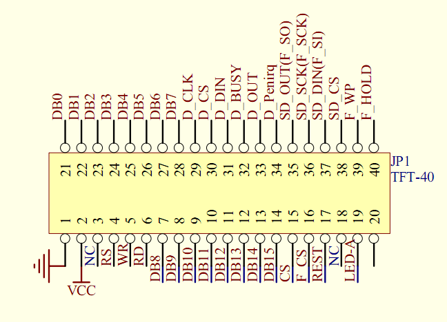
这份是s6d1121的引脚图,其中以D_开头的引脚是用来实现触摸功能的!
其中,D_BUSY在实体屏上标记NC,也就用不到!
也就是说,触摸屏控制线只要5根就行了!
以下几段源码,是定义引脚的功能!
具体的接线就是:
PD3 ------------------ D_DENIRQ
PB14 ---------------- D_CS
PA6 ------------------ D_OUT
PA7 ------------------ D_DIN
PA5 ------------------ D_CLK
还有在touch.h 头文件中,注意以下两条定义:
#define CMD_RDX 0X90
#define CMD_RDY 0XD0
改为
#define CMD_RDX 0XD0
#define CMD_RDY 0X90
不然X ,Y轴数据就反了
要说的就这么多了!
void Touch_Init(void)
{
  	GPIO_InitTypeDef GPIO_InitStructure;

  	RCC_AHB1PeriphClockCmd(RCC_AHB1Periph_GPIOD, ENABLE);
  	GPIO_InitStructure.GPIO_Pin = GPIO_Pin_3;//pen_int:PD3  ---------D_Denirq
  	GPIO_InitStructure.GPIO_Mode = GPIO_Mode_IN;
  	GPIO_InitStructure.GPIO_PuPd = GPIO_PuPd_UP;
  	GPIO_Init(GPIOD, &GPIO_InitStructure);
		SPI1_Init();
		CSPin_init();
}
void SPI1_Init(void)
{
GPIO_InitTypeDef GPIO_InitStructure;
SPI_InitTypeDef SPI_InitStructure;
RCC_APB2PeriphClockCmd(RCC_APB2Periph_SPI1, ENABLE);
RCC_AHB1PeriphClockCmd(RCC_AHB1Periph_GPIOA ,ENABLE);
GPIO_PinAFConfig(GPIOA, GPIO_PinSource5, GPIO_AF_SPI1);
GPIO_PinAFConfig(GPIOA, GPIO_PinSource6, GPIO_AF_SPI1);
GPIO_PinAFConfig(GPIOA, GPIO_PinSource7, GPIO_AF_SPI1);
GPIO_InitStructure.GPIO_Mode = GPIO_Mode_AF;
GPIO_InitStructure.GPIO_OType = GPIO_OType_PP;
GPIO_InitStructure.GPIO_PuPd = GPIO_PuPd_DOWN;
GPIO_InitStructure.GPIO_Speed = GPIO_Speed_50MHz;
GPIO_InitStructure.GPIO_Pin = GPIO_Pin_5 | GPIO_Pin_6 | GPIO_Pin_7;
GPIO_Init(GPIOA, &GPIO_InitStructure);
SPI_I2S_DeInit(SPI1);
SPI_InitStructure.SPI_Direction = SPI_Direction_2Lines_FullDuplex;//全双工
SPI_InitStructure.SPI_DataSize = SPI_DataSize_8b;//8位数据模式
SPI_InitStructure.SPI_CPOL = SPI_CPOL_High;//空闲模式下SCK为1
SPI_InitStructure.SPI_CPHA = SPI_CPHA_2Edge;//数据采样从第2个时间边沿开始
SPI_InitStructure.SPI_NSS = SPI_NSS_Soft;//NSS软件管理
SPI_InitStructure.SPI_BaudRatePrescaler = SPI_BaudRatePrescaler_256;//波特率
SPI_InitStructure.SPI_FirstBit = SPI_FirstBit_MSB;//大端模式
SPI_InitStructure.SPI_CRCPolynomial = 7;//CRC多项式
SPI_InitStructure.SPI_Mode = SPI_Mode_Master;//主机模式
SPI_Init(SPI1, &SPI_InitStructure);
SPI_Cmd(SPI1, ENABLE);
}
void CSPin_init(void)
{
GPIO_InitTypeDef GPIO_InitStructure;
RCC_AHB1PeriphClockCmd(RCC_AHB1Periph_GPIOB | RCC_AHB1Periph_GPIOD, ENABLE);
GPIO_InitStructure.GPIO_Pin = GPIO_Pin_12;//MMACS:PD12
GPIO_InitStructure.GPIO_Mode = GPIO_Mode_OUT;
GPIO_InitStructure.GPIO_OType = GPIO_OType_PP;
GPIO_InitStructure.GPIO_Speed = GPIO_Speed_50MHz;
GPIO_Init(GPIOD, &GPIO_InitStructure);
GPIO_SetBits(GPIOD, GPIO_Pin_12);//不选中
GPIO_InitStructure.GPIO_Pin = GPIO_Pin_14;//TPCS:PB14
GPIO_InitStructure.GPIO_Mode = GPIO_Mode_OUT;
GPIO_InitStructure.GPIO_OType = GPIO_OType_PP;
GPIO_InitStructure.GPIO_Speed = GPIO_Speed_50MHz;
GPIO_Init(GPIOB, &GPIO_InitStructure);
GPIO_SetBits(GPIOB, GPIO_Pin_14);//不选中
GPIO_InitStructure.GPIO_Pin = GPIO_Pin_13;//FLCS:PD13
GPIO_InitStructure.GPIO_Mode = GPIO_Mode_OUT;
GPIO_InitStructure.GPIO_OType = GPIO_OType_PP;
GPIO_InitStructure.GPIO_Speed = GPIO_Speed_50MHz;
GPIO_Init(GPIOD, &GPIO_InitStructure);
GPIO_SetBits(GPIOD, GPIO_Pin_13);//不选中
}

