CCS5.4+Proteus8的F28027实践课七、ADC
吃完饭回来了,现在开始我们的ADC实践操作。
直奔主题我们,那就是ADC编程操作流程是怎么样的。
其实通过上节理论课的学习,大家心里都应该有了模糊的感觉,一般的步骤如下:
1、使能ADC模块时钟( PCLKCR0.ADCENCLK =1)
2、启动模拟电路、带隙和参考源,ADCCTL1寄存器(ADCPWDN, ADCBGPWD, ADCREFPWD位=1)
3、使能ADC模块(ADCCTL1.ADCENABLE=1)
4、ADC中断相关设置(参考PIE)
5、模拟IO引脚复用设置(AIOMUX1)
6、SOC配置(触发、通道、采样窗口)
7、编写中断ISR(读取ADC结果)
了解了操作步骤,那我们就要了解相关的寄存器,由于寄存器又比较多,我这里就不一一讲述,大家直接去看手册就行了

了解了寄存器,下面就要看下具体的操作时序图了:
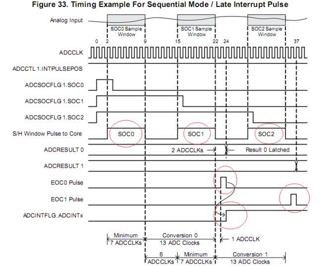
顺序采样的迟中断

顺序采样的早中断

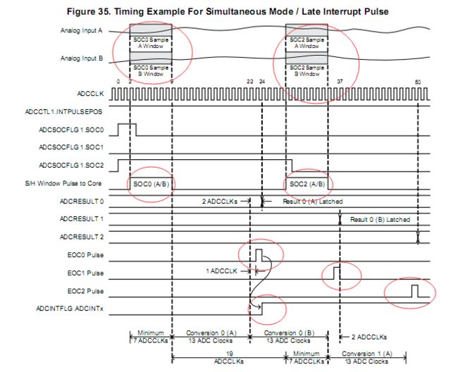
同步采样的迟中断

同步采样的早中断

好了,时序图也看完了,我们现在来参考时序图写程序了。
我们先来个简单的,顺序采样的迟中断。
既然是ADC,那我们这节课肯定用到了TI提供的F2802x_Adc.c文件,另外,还要显示,也需要把我们上节课整理的F2802x_LCD12864.c文件。
首先我们一起来看下ADC初始化函数InitAdc()
void InitAdc(void)
{
    extern void DSP28x_usDelay(Uint32 Count);

    // *IMPORTANT*
    // The Device_cal function, which copies the ADC calibration values from TI reserved
    // OTP into the ADCREFSEL and ADCOFFTRIM registers, occurs automatically in the
    // Boot ROM. If the boot ROM code is bypassed during the debug process, the
    // following function MUST be called for the ADC to function according
    // to specification. The clocks to the ADC MUST be enabled before calling this
    // function.
    // See the device data manual and/or the ADC Reference
    // Manual for more information.

        EALLOW;
        SysCtrlRegs.PCLKCR0.bit.ADCENCLK = 1;
        (*Device_cal)();
        EDIS;

    // To powerup the ADC the ADCENCLK bit should be set first to enable
    // clocks, followed by powering up the bandgap, reference circuitry, and ADC core.
    // Before the first conversion is performed a 5ms delay must be observed
    // after power up to give all analog circuits time to power up and settle

    // Please note that for the delay function below to operate correctly the
    // CPU_RATE define statement in the DSP2802x_Examples.h file must
    // contain the correct CPU clock period in nanoseconds.
    EALLOW;
    AdcRegs.ADCCTL1.bit.ADCBGPWD  = 1;      // Power ADC BG
    AdcRegs.ADCCTL1.bit.ADCREFPWD = 1;      // Power reference
    AdcRegs.ADCCTL1.bit.ADCPWDN   = 1;      // Power ADC
    AdcRegs.ADCCTL1.bit.ADCENABLE = 1;      // Enable ADC
    AdcRegs.ADCCTL1.bit.ADCREFSEL = 0;      // Select interal BG
    EDIS;

    DELAY_US(ADC_usDELAY);         // Delay before converting ADC channels
}
初始化函数已经把我们的前三步都做完了,也就是使能时钟、上电、使能ADC模块;
那我们现在来进行SOC相关设置,也就是:触发源、采样时隙、通道选择。
触发源我们选择定时器0,因为我们做测试肯定输入一个稳定的直流电压,那用定时器最方便。
AdcRegs.ADCSOC0CTL.bit.TRIGSEL = 1;
采样时隙就用最短时隙,也就是AdcRegs.ADCSOC0CTL.bit.ACQPS = 6;
由于TI那个实验板只引出了几个ADC引脚而已,我们就用ADCINA1,也就是AdcRegs.ADCSOC0CTL.bit.CHSEL = 1;
另外,我们说了,我们本次的实验是顺序采样,迟中断,那就是:
AdcRegs.ADCSAMPLEMODE.bit.SIMULEN0 = 1;
AdcRegs.ADCCTL1.bit.INTPULSEPOS = 1;
到这里SOC相关设置就完成了,我们现在开始要对PIE中断就行相应的设置了。
我们这里采用简单的中断1,EOC脉冲触发ADCINTx脉冲
AdcRegs.INTSEL1N2.bit.INT1SEL = 0;
AdcRegs.INTSEL1N2.bit.INT1CONT = 1;
AdcRegs.INTSEL1N2.bit.INT1E = 1;
最后还要再PIE组里面打开ADCINT1开关:PieCtrlRegs.PIEIER1.bit.INTx1 = 1;
ADC中断函数就一个置位:
interrupt void ADCINT1_ISR(void)   // ADC  (Can also be ISR for INT10.1 when enabled)
{
  // Insert ISR Code here

  // To receive more interrupts from this PIE group, acknowledge this interrupt
   PieCtrlRegs.PIEACK.all = PIEACK_GROUP1;

  // Next two lines for debug only to halt the processor here
  // Remove after inserting ISR Code

  //asm ("      ESTOP0");
  //for(;;);

}
ADC中断也说完了,还有定时器设置,这个就参考我们前面写的那个程序,一模一样,也就是说采样时隙是1ms
首先是CPU.c文件
void InitCpuTimers(void)
{
    // CPU Timer 0
    // Initialize address pointers to respective timer registers:
    CpuTimer0.RegsAddr = &CpuTimer0Regs;
    // Initialize timer period to maximum:
    CpuTimer0Regs.PRD.all  = 1000;
    // Initialize pre-scale counter to divide by 1 (SYSCLKOUT):
    CpuTimer0Regs.TPR.bit.TDDR  = 59;
    CpuTimer0Regs.TPRH.bit.TDDRH = 0;
    // Make sure timer is stopped:
    CpuTimer0Regs.TCR.bit.TSS = 1;
    // Reload all counter register with period value:
    CpuTimer0Regs.TCR.bit.TRB = 1;
    // Reset interrupt counters:
    CpuTimer0.InterruptCount = 0;

// CpuTimer 1 and CpuTimer2 are reserved for DSP BIOS & other RTOS
// Do not use these two timers if you ever plan on integrating
// DSP-BIOS or another realtime OS.
//
// Initialize address pointers to respective timer registers:
    CpuTimer1.RegsAddr = &CpuTimer1Regs;
    CpuTimer2.RegsAddr = &CpuTimer2Regs;
    // Initialize timer period to maximum:
    CpuTimer1Regs.PRD.all  = 0xFFFFFFFF;
    CpuTimer2Regs.PRD.all  = 0xFFFFFFFF;
    // Initialize pre-scale counter to divide by 1 (SYSCLKOUT):
    CpuTimer1Regs.TPR.all  = 0;
    CpuTimer1Regs.TPRH.all = 0;
    CpuTimer2Regs.TPR.all  = 0;
    CpuTimer2Regs.TPRH.all = 0;
    // Make sure timers are stopped:
    CpuTimer1Regs.TCR.bit.TSS = 1;
    CpuTimer2Regs.TCR.bit.TSS = 1;
    // Reload all counter register with period value:
    CpuTimer1Regs.TCR.bit.TRB = 1;
    CpuTimer2Regs.TCR.bit.TRB = 1;
    // Reset interrupt counters:
    CpuTimer1.InterruptCount = 0;
    CpuTimer2.InterruptCount = 0;

}
然后是定时中断函数
interrupt void  TINT0_ISR(void)      // CPU-Timer 0
{
  // Insert ISR Code here

  // To receive more interrupts from this PIE group, acknowledge this interrupt
  PieCtrlRegs.PIEACK.all = PIEACK_GROUP1;

  // Next two lines for debug only to halt the processor here
  // Remove after inserting ISR Code
//  asm ("      ESTOP0");
//  for(;;);
}
最后是相关中断设置
   CpuTimer0Regs.TCR.bit.TIE = 1;
   StartCpuTimer0();
   EALLOW;
   PieCtrlRegs.PIEIER1.bit.INTx7 = 1;
   PieCtrlRegs.PIECTRL.bit.ENPIE = 1;
   IER |= 0x0001;
   EINT;
   EDIS;
现在定时中断也写完了,就剩下ADC处理显示函数了
   while(1)
   {
       if(AdcRegs.ADCSOCFLG1.bit.SOC0==1)
       {
           while(AdcRegs.ADCSOCFLG1.bit.SOC0==1);
           AdcRegs.ADCINTFLGCLR.bit.ADCINT1 = 1;
           DELAY_US(10);
           sum+=AdcResult.ADCRESULT0;
           i++;
       }
       if(i==100)
       {
           sum/=100;
           vol=sum*3.3/4095;
           WRITECMD_LCD12864(0x01);
           DISLPLAY_LONGSTRING(2,0,sum);
           DISLPLAY_FLOATSTRING(3,0,vol);
           WRITEDATA_LCD12864('v');
           sum=0;
           i=0;
       }
   }
我是直接写在while死循环里面的,然后去捕捉转换标志位,采样100次,取平均值。
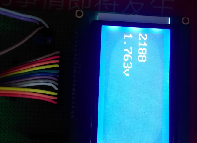
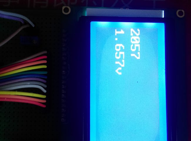
下载程序验证,成功,呵呵,上大家上效果图


突然想到一个刚才调试的问题,就是提示我.text段超出空间,我把段大小相应调整了下
.text : > PRAML0, PAGE = 0
PRAML0 : origin = 0x008000, length = 0x000c00
DRAML0 : origin = 0x008c00, length = 0x000400
具体的代码我会传到下载库和QQ群里面,大家有需要的话自行下载
菜鸟交流qq群107691092