TMS320C6455的EMIF外部存储器接口
DSP6455的EMIFA模块
前言:
C6455的EMIFA可以访问多种外部存储器,比如:SRAM,ROM,FLASH等等。当然,也包括FPGA。本文的重点就是介绍使用EMIFA接口与FPGA建立无缝连接以及和FLASH的连接。
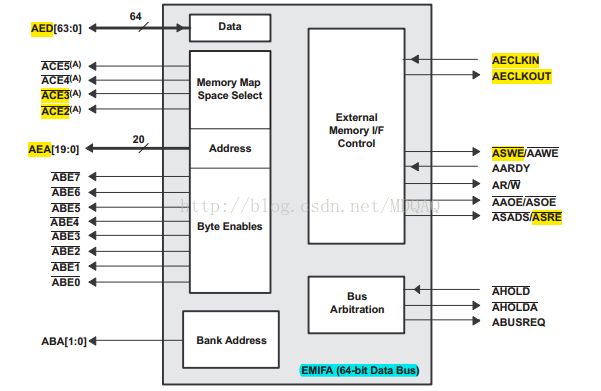
1.EMIF接口信号图
部分管脚说明:
•AED[63:0] 64位数据总线
•AEA[19:0] 20位地址总线(Optional)
•ACE2 片选信号(低有效)
•ACE3 片选信号(低有效)
•AECLKOUT 时钟信号
•ASWE 写使能(低有效)
•ASRE 读使能(低有效)
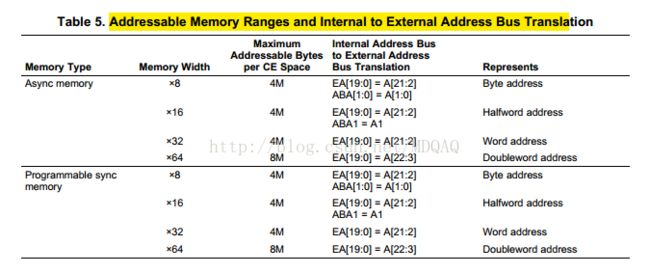
2.EMIF片选信号及映射情况
从图中可以看出:
•EMIFA共支持4个外部存储器,例如把CE2分配给FPGA,CE3分配给FLASH。
•每个外部存储器的寻址空间大小是8MB。FPGA20根地址线即2的20次方,也就是1MB,此外由于数据总线是64位的,故对应的寻址空间是8MB(但是在这里FLASH我们配置的是8位内存位宽,所以此处是4M寻址空间)
在读取FPGA内部RAM数据时告诉EDMA要读取的数据的基地址是0xA0000000,以及读取的数据的长度即可。
在读取FLASH数据时告诉EDMA要读取的数据的基地址是0xB0000000,以及读取的数据的长度即可。
3.EMIF与 FPGA和FLASH连接原理图
EMIF:
FPGA:
FLASH:
4.配置EMIFA的寄存器
主要配置寄存器是CEnCFG。该寄存器有两套完全不同的配置,分别对应于同步存储器模式和异步存储器模式。由于FPGA内部RAM工作于同步模式,故我们来看一下同步模式下该寄存器的配置。FLASH则是采用异步模式。
(1)异步模式的外部存储器(高亮部分)FLASH配置
(2)同步模式的外部存储器(高亮部分)FPGA配置
5.代码编写
配置EMIFA模块时,主要的步骤如下:
(1) 使能设备EMIFA模块
(2) 配置CEnCFG寄存器
(3) 初始化EMIFA模块
#define EMIFA_BASE_ADDR (0x70000000)

#define EMIFA_MIDR     (*(int*)(EMIFA_BASE_ADDR + 0x00000000))
#define EMIFA_STAT     (*(int*)(EMIFA_BASE_ADDR + 0x00000004))
#define EMIFA_BPRIO    (*(int*)(EMIFA_BASE_ADDR + 0x00000020))
#define EMIFA_CE2CFG   (*(int*)(EMIFA_BASE_ADDR + 0x00000080))
#define EMIFA_CE3CFG   (*(int*)(EMIFA_BASE_ADDR + 0x00000084))
#define EMIFA_CE4CFG   (*(int*)(EMIFA_BASE_ADDR + 0x00000088))
#define EMIFA_CE5CFG   (*(int*)(EMIFA_BASE_ADDR + 0x0000008C))
#define EMIFA_AWCC     (*(int*)(EMIFA_BASE_ADDR + 0x000000A0))

void init_emif(void)
{
	/* Enable the async EMIF and the DDR2 Memory Controller */
	*(int *)(0x02AC002C) = 0x00000003;  // PERCFG1 = 0x02AC002C

	/* Configure async EMIF */
	//EMIFA_CE2CFG = 0x80240122; /* 32-bit sync, 10 cycle read/write strobe   for fpga A0000000 - A07FFFFF */
	EMIFA_CE2CFG = 0x8000000A; /* 32-bit sync, write latency 0 read latency 2  */
	EMIFA_CE3CFG = 0x00240120; /* 8-bit async, 10 cycle read/write strobe  for norflash */

	//EMIFA_CE4CFG = 0x00240122; /* 32-bit async, 10 cycle read/write strobe for fpga*/

	//EMIFA_CE4CFG = 0x00240121; /* 16-bit Async,  read/write strobe for fpga*/
   	//EMIFA_CE5CFG = 0x80240122; /* 32-bit async, 10 cycle read/write strobe */

	EMIFA_BPRIO  = 0x000000FE; /* Enable priority based starvation control SPRU971A sec. 7.2 */
	EMIFA_AWCC   = 0x000002FF; //TA 2 clock,
}
代码说明:
FPGA:
#define EMIF_FPGA_BASE_ADDR    0xA0000000

void WriteFpga(Uint32 addr,Uint32 data)
{


	*((Uint32*) (EMIF_FPGA_BASE_ADDR + addr))  = data;

}

Uint32 ReadFpga(Uint32 addr)
{

	Uint32 reData = 0;

	reData = *((Uint32*) (EMIF_FPGA_BASE_ADDR + addr));
	return reData;

}

Uint32 emif_test(Uint32 addr, Uint8 *data, Uint32 len)
{
	int num;
	Uint32 readData;
	Uint32 startData = 0x11111111;
	Uint32 writeData;

	for(num = 0; num < 256 / 4; num++)
	{
		writeData = startData + num;
		WriteFpga(num * 4, writeData);
		readData =ReadFpga(num * 4);
		if(readData != writeData)
		{
			printf("write = %X read = %X\n", writeData, readData);
		}
	}
	printf("emif test OK! \n");

	return 0;
}
FLASH:
#define FLASH_BASE                   0xB0000000
#define FLASH_RESET                         0xF0
#define FLASH_CMD_AA                        0xAA
#define FLASH_CMD_55                        0x55
#define FLASH_PROGRAM                       0xA0
#define FLASH_PROGRAM_BUFFER                0x29
#define FLASH_ERASE                         0x80
#define FLASH_ERASE_CHIP                    0x10
#define FLASH_ERASE_SECTOR                  0x30
#define FLASH_ERASE_SUSPEND                 0xB0
#define FLASH_ERASE_RESUME                  0x10


int norflash_erase( Uint32 start, Uint32 length )
{
    Uint16 i;
    Uint8 *pdata;
    Uint32 sector_base,end;


    end = start + length - 1;                   // Calculate end of rang

  /* Walk through each sector, erase any sectors within range */
    sector_base = FLASH_BASE;
    for (i = 0; i < FLASH_SECTORS; i++)
    {
        if ( ( ( sector_base >= start ) || ( sector_end[i] >= start ) ) &&
             ( ( sector_base <= end )   || ( sector_end[i] <= end ) ) )
        {
            /* Start sector erase sequence */
            FLASH_CTL555 = FLASH_CMD_AA;
            FLASH_CTL2AA = FLASH_CMD_55 ;
            FLASH_CTL555 = FLASH_ERASE;
            FLASH_CTL555 = FLASH_CMD_AA;
            FLASH_CTL2AA = FLASH_CMD_55 ;

            /* Start erase at sector address */
            pdata = (Uint8 *)sector_base;
            *pdata = FLASH_ERASE_SECTOR;

            /* Wait for erase to complete */
            while (1)
                if (*pdata & 0x80)
                    break;

            /* Put back in read mode */
            *((Uint8 *)FLASH_BASE) = FLASH_RESET;
        }

        /* Advance to next sector */
        sector_base = sector_end[i] + 1;
    }
    *((Uint8 *)FLASH_BASE) = FLASH_RESET;
    return 0;
}

int norflash_write( Uint8* src, Uint32 dst, Uint32 length )
{
    Uint32 i;
    Uint8* psrc8;
    Uint8* pdst8;
    volatile Uint8* addr8  = ( Uint8* )FLASH_BASE;
    /*
     *  Align to 8 or 8 bits
     */
    psrc8 = ( Uint8* )src;
    pdst8 = ( Uint8* )dst;

     for ( i = 0 ; i < length ; i ++ )
     {
         /* Program one 8-bit word */
         FLASH_CTL555 = FLASH_CMD_AA;
         FLASH_CTL2AA = FLASH_CMD_55;
         FLASH_CTL555 = FLASH_PROGRAM;
         *pdst8 = *psrc8;

         /* Wait for programming to complete */
         // Wait for operation to complete
         while(1)
             if (*pdst8 == *psrc8)
                 break;
         pdst8++;
         psrc8++;
     }

    *addr8 = FLASH_RESET;
    return 0;
}

int norflash_read( Uint32 src, Uint8* dst, Uint32 length )
{
    Uint32 i;
    Uint8* psrc8 = ( Uint8* )src;
    Uint8* pdst8 = ( Uint8* )dst;

    /*
     *  Set to Read Mode
     */
    FLASH_BASE_PTR8 = FLASH_RESET;

    /*
     *  Read Data to Buffer
     */
    for ( i = 0 ; i < length ; i ++ )
        *pdst8++ = *psrc8++;

    return 0;
}

int norflash_test(Uint32 dstAddr, Uint32 length, Uint8 start)
{
	int retVal;
    Uint32 num;
	Uint32 wLen;
    Uint8 data;
    Uint8 *testData = NULL;

	testData = (Uint8*)malloc(1024);
	if(testData == NULL)
	{
		printf("malloc is error!\n");
		return -1;
	}

	for(num = 0; num < 1024; num++)
	{
		testData[num] = start + num;
	}

	norflash_erase(dstAddr, length);

	while(length > 0)
	{
		wLen = length > 1024 ? 1024 : length;
		length -= wLen;
		retVal = norflash_write(testData, dstAddr, wLen);
		if(retVal != 0)
		{
			printf("nor flash write is error!\n");
			return -1;
		}

		memset(testData, 0, wLen);

		retVal = norflash_read(dstAddr, testData, wLen);
		if(retVal != 0)
		{
			printf("nor flash write is error!\n");
			return -1;
		}


		for(num = 0; num < wLen; num++)
		{
			data = start + num;
			if(testData[num] != data)
			{
				printf("nor flash test is error!\n");
				return -1;
			}
		}

		dstAddr += wLen;
	}


	printf("nor flash test is ok!\n");
	return 0;

}
FLASH代码说明:
参看:http://blog.csdn.net/mdqaq/article/details/53606900


