Openwrt:基于MT7628/MT7688的PWM驱动
前言
MT7628/MT7688的PWM驱动相关资料较少,官方的datasheet基本也是一堆寄存器,啃了许久,终于嚼出了味道。由于PWM存在IO口复用的问题,所以要提前配置好GPIO的工作方式,不然你无论怎么掐示波器,都不会出现预计的波形。由于MT7688和MT7628是pin to pin,几乎完全兼容,除了MT7628是2T2R而MT7688是1T1R这个区别,在PWM的设置上是相同,所以MT7688也可以直接参考MT7628的编程手册。
寄存器
pwm复用关系
MT7688最多支持四路PWM,分别是pwm_ch0、pwm_ch1、pwm_ch2、pwm_ch3,从MT7688的pin map可知:
- pwm_ch0、pwm_ch1复用在PAD_MDI_TP_P1和PAD_MDI_TN_P1上,也就是网口1的传输线,再往下看,pwm_ch0、pwm_ch1还复用在txd1、rxd1上,这是串口1;
- pwm_ch2、pwm_ch3复用在PAD_MDI_TP_P2和PAD_MDI_TN_P2上,也就是网口2;
由上面如果既要使用网口1的功能,又要使用pwm_ch0、pwm_ch1的功能,那么必须复用到txd1和rxd1上才可以,因为系统默认GPIO14、15的功能是网口1,而GPIO45、46的功能是串口1,所以这里还需对GPIO的模式进行配置,同理pwm_ch2、pwm_ch3也需要进行类似的配置。
gpio mode
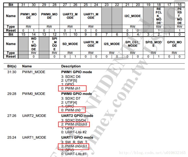
选择那几路pwm做为这几个GPIO的功能则需要配置GPIO_MODE寄存器了,由下图可知,GPIO被分为两组,分别为GPIO1与GPIO2,寄存器地址分别为10000060和10000064这在后面驱动编写对GPIO进行初始化的时候会用到。
![]()
下图是GPIO1的寄存器配置方式,在此可知,对于PWM的选择只需配置相应的Bit即可。不同的模式通过不同的值进行选择。

代码
以下驱动代码参考了小鱼儿专栏的博文,做了部分修改,修复了几处错误,经测试可以使用。
mt7688_pwm.c
#include
#include
#include
#include
#include
#include
#include
#include
#include
#include
#include
#include
#include
#include
#include
#include
#include
#include

#include "mt7688_pwm.h"

MODULE_LICENSE("GPL");

#define RALINK_CLK_CFG    0xB0000030
#define RALINK_AGPIO_CFG  0xB000003C
#define RALINK_GPIOMODE   0xB0000060

#define RALINK_PWM_BASE   0xB0005000

//#define RALINK_CLK_CFG    0x10000030
//#define RALINK_AGPIO_CFG  0x1000003C
//#define RALINK_GPIOMODE   0x10000060
//#define RALINK_PWM_BASE   0x10005000
#define RALINK_PWM_ENABLE    RALINK_PWM_BASE

#define PWM_MODE_BIT      15
#define PWM_GVAL_BIT      8
#define PWM_IVAL_BIT      7

enum {
    PWM_REG_CON,
    PWM_REG_GDUR = 0x0C,
    PWM_REG_WNUM = 0x28,
    PWM_REG_DWID = 0x2C,
    PWM_REG_THRE = 0x30,
    PWM_REG_SNDNUM = 0x34,
}PWM_REG_OFF;

#define PWM_NUM  4
u32 PWM_REG[PWM_NUM] = {
    (RALINK_PWM_BASE + 0x10),    /* pwm0 base */
    (RALINK_PWM_BASE + 0x50),    /* pwm1 base */
    (RALINK_PWM_BASE + 0x90),    /* pwm2 base */
    (RALINK_PWM_BASE + 0xD0)     /* pwm3 base */
};

#define NAME  "sooall_pwm"

int pwm_major;
int pwm_minor  = 0;
int pwm_device_cnt = 1;
struct cdev pwm_cdev;

static struct class  *pwm_class;
static struct device *pwm_device;

spinlock_t pwm_lock;

static void sooall_pwm_cfg(struct pwm_cfg *cfg)
{
    u32 value;
    unsigned long  flags;
    u32 basereg;

    basereg = PWM_REG[cfg->no];

    spin_lock_irqsave(&pwm_lock, flags);

    /* 1. set the pwm control register */
    value  = le32_to_cpu(*(volatile u32 *)(basereg + PWM_REG_CON));
    /* old mode */
    value |= (1 << PWM_MODE_BIT);
    /* set the idel val and guard val */
    value &= ~((1 << PWM_IVAL_BIT) | (1 << PWM_GVAL_BIT));
    value |= ((cfg->idelval & 0x1) << PWM_IVAL_BIT);
    value |= ((cfg->guardval & 0x1) << PWM_GVAL_BIT);
    /* set the source clk */
    if (cfg->clksrc == PWM_CLK_100KHZ) {
        value &= ~(1<<3);
    } else {
        value |= (1<<3);
    }
    /* set the clk div */
    value &= ~0x7;
    value |= (0x7 & cfg->clkdiv);
    *(volatile u32 *)(basereg + PWM_REG_CON) = cpu_to_le32(value);

    /* 2. set the guard duration val */
    value  = le32_to_cpu(*(volatile u32 *)(basereg + PWM_REG_GDUR));
    value &= ~(0xffff);
    value |= (cfg->guarddur & 0xffff);
    *(volatile u32 *)(basereg + PWM_REG_GDUR) = cpu_to_le32(value);


    /* 3. set the wave num val */
    value  = le32_to_cpu(*(volatile u32 *)(basereg + PWM_REG_WNUM));
    value &= ~(0xffff);
    value |= (cfg->wavenum & 0xffff);
    *(volatile u32 *)(basereg + PWM_REG_WNUM) = cpu_to_le32(value);


    /* 4. set the data width val */
    value  = le32_to_cpu(*(volatile u32 *)(basereg + PWM_REG_DWID));
    value &= ~(0x1fff);
    value |= (cfg->datawidth & 0x1fff);
    *(volatile u32 *)(basereg + PWM_REG_DWID) = cpu_to_le32(value);


    /* 5. set the thresh  val */
    value  = le32_to_cpu(*(volatile u32 *)(basereg + PWM_REG_THRE));
    value &= ~(0x1fff);
    value |= (cfg->threshold & 0x1fff);
    *(volatile u32 *)(basereg + PWM_REG_THRE) = cpu_to_le32(value);

    spin_unlock_irqrestore(&pwm_lock, flags);
}

static void sooall_pwm_enable(int no)
{
    u32 value;
    unsigned long  flags;

    printk(KERN_INFO NAME "enable pwm%d\n", no);

    spin_lock_irqsave(&pwm_lock, flags);
    value  = le32_to_cpu(*(volatile u32 *)(RALINK_PWM_ENABLE));
    value  |= (1 << no);
    *(volatile u32 *)(RALINK_PWM_ENABLE) = cpu_to_le32(value);
    spin_unlock_irqrestore(&pwm_lock, flags);
}

static void sooall_pwm_disable(int no)
{
    u32 value;
    unsigned long  flags;

    printk(KERN_INFO NAME "disable pwm%d\n", no);

    spin_lock_irqsave(&pwm_lock, flags);
    value  = le32_to_cpu(*(volatile u32 *)(RALINK_PWM_ENABLE));
    value  &= ~(1 << no);
    *(volatile u32 *)(RALINK_PWM_ENABLE) = cpu_to_le32(value);
    spin_unlock_irqrestore(&pwm_lock, flags);
}

static void sooall_pwm_getsndnum(struct pwm_cfg *cfg)
{
    u32 value;
    unsigned long  flags;
    u32 regbase = PWM_REG[cfg->no];

    spin_lock_irqsave(&pwm_lock, flags);
    value  = le32_to_cpu(*(volatile u32 *)(regbase + PWM_REG_SNDNUM));
    cfg->wavenum = value;
    spin_unlock_irqrestore(&pwm_lock, flags);
}

#if LINUX_VERSION_CODE > KERNEL_VERSION(2,6,35)
long sooall_pwm_ioctl(struct file *file, unsigned int req,
        unsigned long arg)
#else
int sooall_pwm_ioctl(struct inode *inode, struct file *file, unsigned int req,
        unsigned long arg)
#endif
{
    switch (req) {
    case PWM_ENABLE:
        sooall_pwm_enable(((struct pwm_cfg *)arg)->no);
        break;
    case PWM_DISABLE:
        sooall_pwm_disable(((struct pwm_cfg *)arg)->no);
        break;
    case PWM_CONFIGURE:
        sooall_pwm_cfg((struct pwm_cfg *)arg);
        break;
    case PWM_GETSNDNUM:
        sooall_pwm_getsndnum((struct pwm_cfg *)arg);
        break;
    default:
        return -ENOIOCTLCMD;
    }

    return 0;
}

static int sooall_pwm_open(struct inode * inode, struct file * filp)
{
    return 0;
}

static int sooall_pwm_close(struct inode *inode, struct file *file)
{
    return 0;
}

static const struct file_operations pwm_fops = {
    .owner      = THIS_MODULE,
#if LINUX_VERSION_CODE > KERNEL_VERSION(2,6,35)
    unlocked_ioctl:sooall_pwm_ioctl,
#else
    ioctl:sooall_pwm_ioctl,
#endif
    .open       = sooall_pwm_open,
    .release    = sooall_pwm_close,
};

static int setup_chrdev(void)
{
    dev_t dev;
    int err = 0;

    if (pwm_major) {
        dev = MKDEV(pwm_major, 0);
        err = register_chrdev_region(dev, pwm_device_cnt, NAME);
    } else {
        err = alloc_chrdev_region(&dev, 0, pwm_device_cnt, NAME);
        pwm_major = MAJOR(dev);
    }

    if (err < 0) {
        printk(KERN_ERR NAME "get device number failed\n");
        return -1;
    }

    cdev_init(&pwm_cdev, &pwm_fops);
    pwm_cdev.owner = THIS_MODULE;
    pwm_cdev.ops = &pwm_fops;
    err = cdev_add(&pwm_cdev, dev, pwm_device_cnt);
    if (err < 0) {
        printk(KERN_ERR NAME "cdev_add failed\n");
        unregister_chrdev_region(dev, pwm_device_cnt);
        return -1;
    }

    return 0;
}

static void clean_chrdev(void)
{
    dev_t dev = MKDEV(pwm_major, 0);

    cdev_del(&pwm_cdev);
    unregister_chrdev_region(dev, pwm_device_cnt);
}

static void setup_gpio(void)
{
    u32 value;
    int i = 0;
    /* pwm0 pwm1 */

    /* enable the pwm clk */
    value  = le32_to_cpu(*(volatile u32 *)(RALINK_CLK_CFG));
    value  |= (1 << 31);
    *(volatile u32 *)(RALINK_CLK_CFG) = cpu_to_le32(value);

    /* set the agpio cfg of ephy_gpio_aio_en */
    //value  = le32_to_cpu(*(volatile u32 *)(RALINK_AGPIO_CFG));
    //value  |= (0xF<<17);
    //*(volatile u32 *)(RALINK_AGPIO_CFG) = cpu_to_le32(value);

    /* set the pwm  mode */
    //value  = le32_to_cpu(*(volatile u32 *)(RALINK_GPIOMODE));
    //value  &= ~(3 << 28 | 3 << 30);
    //*(volatile u32 *)(RALINK_GPIOMODE) = cpu_to_le32(value);

   value  = le32_to_cpu(*(volatile u32 *)(RALINK_GPIOMODE));
   value  |= (2 << 24);

   *(volatile u32 *)(RALINK_GPIOMODE) = cpu_to_le32(value);

    /* disable all the pwm */
    for (i = 0; i < PWM_NUM; i++) {
        sooall_pwm_disable(i);
    }
}

static int sooall_pwm_init(void)
{
    int ret = 0;

    spin_lock_init(&pwm_lock);

    ret = setup_chrdev();
    if (ret < 0)
        return -1;

    pwm_class = class_create(THIS_MODULE, NAME);
    if (NULL == pwm_class) {
        printk(KERN_ERR NAME "class_create failed\n");
        goto dev_clean;
    }

    pwm_device = device_create(pwm_class, NULL,
                    MKDEV(pwm_major, pwm_minor), NULL, "sooall_pwm");
    if (NULL == pwm_device) {
        printk(KERN_ERR NAME "device_create failed\n");
        goto class_clean;
    }

    setup_gpio();

    printk(KERN_INFO "sooall pwm init success\n");
    return 0;

class_clean:
    class_destroy(pwm_class);
dev_clean:
    clean_chrdev();
    return -1;
}

static void sooall_pwm_exit(void)
{
    device_destroy(pwm_class, MKDEV(pwm_major, pwm_minor));
    class_destroy(pwm_class);
    clean_chrdev();
    printk(KERN_INFO "sooall pwm exit\n");
}

module_init(sooall_pwm_init);
module_exit(sooall_pwm_exit);
mt7688_pwm.h
#ifndef _SOOALL_PWM_H_
#define _SOOALL_PWM_H_

/* the source of the clock */
typedef enum {
    PWM_CLK_100KHZ,
    PWM_CLK_40MHZ
}PWM_CLK_SRC;

/* clock div */
typedef enum {
    PWM_CLI_DIV0 = 0,
    PWM_CLK_DIV2,
    PWM_CLK_DIV4,
    PWM_CLK_DIV8,
    PWM_CLK_DIV16,
    PWM_CLK_DIV32,
    PWM_CLK_DIV64,
    PWM_CLK_DIV128,
}PWM_CLK_DIV;

struct pwm_cfg {
    int no;
    PWM_CLK_SRC    clksrc;
    PWM_CLK_DIV    clkdiv;
    unsigned char  idelval;
    unsigned char  guardval;
    unsigned short guarddur;
    unsigned short wavenum;
    unsigned short datawidth;
    unsigned short threshold;
};

/* ioctl */
#define PWM_ENABLE      0
#define PWM_DISABLE     1
#define PWM_CONFIGURE   2
#define PWM_GETSNDNUM   3
#endif
How to use it?
下载源码
压缩包中包含两个压缩包分别是mt7688_pwm.tar.gz、mt7688_pwm_app.tar.gz,驱动和测试程序。
并解压缩到openwrt 15.01 SDK的Package/下。进行编译即可。
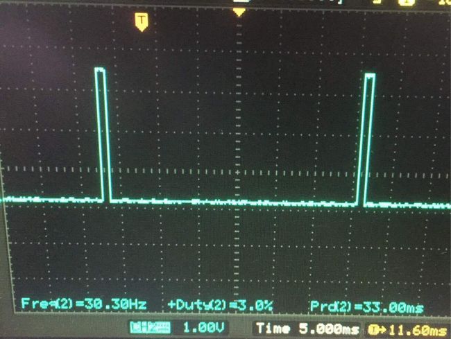
最后附一张成功的图片^_^

