linux IRQ Management(二)- ARM异常模式
- 学习异常、中断模式。
1.ARM工作模式
ARM有7种工作模式,分别是用户模式(user)、快速中断模式(fiq)、外部中断模式(irq)、管理模式(svc)、中止模式(abt)、未定义指令模式(und)和系统模式(sys)。除去用户模式和系统模式以外,其余5种模式称为异常模式,常用于处理中断或异常,以及需要访问受保护的系统资源等情况。如下所示:
- User – Normal program execution mode
- FIQ – Supports a high-speed data transfer or channel process
- IRQ – Used for general-purpose interrupt handling
- Supervisor --A protected mode for the operating system
- Abort – Implements virtual memory and/or memory protection
- Undefined – Supports software emulation of hardware coprocessors
- System – Runs privileged operating system tasks
工作模式大类分为User mode和privileged modes。
- User mode,Most application programs execute in User mode. When the processor is in User mode, the program being executed is unable to access some protected system resources or to change mode, other than by causing an exception to occur.
- Privileged modes(other than User mode),They have full access to system resources and can change mode freely. Five of them are known as exception modes:
- FIQ
- IRQ
- Supervisor
- Abort
- Undefined
2.异常
2.1.Exceptions Introduction
An exception is any condition that requires the core to stop normal execution and instead execute a dedicated software routine that is known as an exception handler.
Exceptions are generated by internal and external sources to cause the processor to handle an event, such as an externally generated interrupt or an attempt to execute an Undefined instruction. The processor state just before handling the exception is normally preserved so that the original program can be resumed when the exception routine has completed. More than one exception can arise at the same time.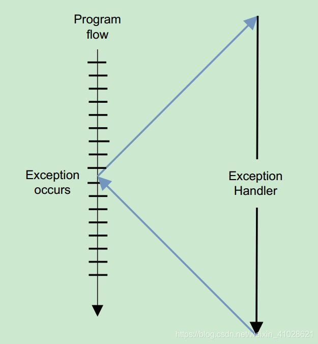
The ARM architecture supports seven types of exception. When an exception occurs, execution is forced from a fixed memory address corresponding to the type of exception. These fixed addresses are called the exception vectors.
2.2.Exceptions types
 2.3.异常优先级

2.4.Exception classify
Asynchronous events are those that can occur at any time and typically occur at unanticipated spots of the running program, while synchronous events are those that can occur only at planned or anticipated spots of the running program.
- synchronous:
- Abort
- SWI
- Undefined
- asynchronous:
- IRQ
- FIQ
2.4.1.IRQ
The IRQ exception is generated externally by asserting the IRQ input on the processor. It has a lower priority than FIQ.
2.4.2.FIQ
Fast Interrupt Requests (FIQs) are a specialized type of Interrupt Request, a standard technique used in computer CPUs to deal with events which need to be processed as they occur such as receiving data from a network card, or keyboard or mouse actions. FIQs are specific to the ARM CPU architecture, which supports two types of interrupts; FIQs for fast, low latency interrupt handling and Interrupt Requests (IRQs), for more general interrupts
An FIQ takes priority over an IRQ in an ARM system. Also, only one FIQ source at a time is supported. This helps reduce interrupt latency as the interrupt service routine can be executed directly without determining the source of the interrupt. A context save is not required for servicing an FIQ since it has its own set of banked registers. This reduces the overhead of context switching.
2.5.Vector table
To aid in handling exceptions and interrupts, each architecturally defined exception and each interrupt condition requiring special handling by the processor is assigned a unique identification number, called a vector number. The
processor uses the vector number assigned to an exception or interrupt as an index into the interrupt descriptor table (IDT). The table provides the entry point to an exception or interrupt handler.
Two approaches for a microprocessor to locate the ISR of an interrupting device:
- nonvectored interrupting
- vectored interrupting
Difference between vectored and non vectored interrupts
In a non-vectored interrupt, the peripheral itself provides the address of the interrupt service routine directly to the processor. This requires more time for an interrupt to be serviced, since the address must be retrieved from the interrupting device every time the interrupt is triggered.
A vectored interrupt is where the CPU actually knows the address of the Interrupt Service Routine in advance. All it needs is that the interrupting device sends its unique vector via a data bus and through its I/O interface to the CPU. The CPU takes this vector, checks an interrupt table in memory, and then carries out the correct ISR for that device. So the vectored interrupt allows the CPU to be able to know what ISR to carry out in software (memory).
2.5.1.Nonvectored Interrupting
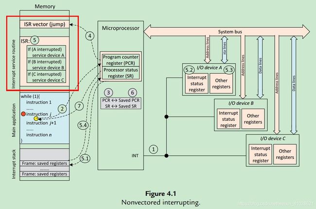
1.While the processor is executing an instruction j of a user program, one of the I/O devices raises an IRQ signal to the interrupt input pin (INT).
2. The processor detects the IRQ. Upon the completion of the instruction j, the processor starts an interrupt acknowledge cycle. At this point, the value contained by the program counter register (PCR) is the location of the next instruction of the user program.
3. In the interrupt acknowledge cycle, the status register (SR) and the PCR are saved (say, into spare registers) so that the user program can be resumed later.
4. The PCR is loaded with the fixed memory location where the common interrupt vector is saved.
5. This common interrupt vector is typically a jump instruction, pointing to the start location of the ISR.
- Inside the ISR, the commonly used registers are first saved onto the interrupt stack. In so doing, the processor switches its context from the user task to the ISR.
- Next, the processor searches through the devices, from high priority to low priority,to identify the interrupt source (requesting device). An I/O device often has one or more interrupt status registers that latch its IRQ; the processor can check such registers to ensure IRQs are not missed.
- The portion of code pertinent to the requesting device is executed, which typically entails the access of the ports (registers) on the device.
- At the end of the ISR, the top frame of the interrupt stack is popped up and the context of the user task is restored.
6.The original PCR value is restored.
7.The processor is ready to run the next instruction of the user program.
2.5.2. Vectored Interrupting
In vectored interrupting, a special block of memory is typically reserved to accommodate a data structure called an interrupt vector table—a table with a sequence of entries called interrupt vectors. Each interrupt vector contains information that points the processor to the start address of the corresponding ISR.
 1. Device A drives an IRQ on the IRQ0 line of the PIC.
2. The PIC detects the IRQ on IRQ0. It frst converts the request into a vector number corresponding to device A, stores it in a register, and then asserts the INT line to inform the processor.
3. While the instruction j of the current program is being executed, the processor samples INT and detects an asserted line. After the execution of the instruction j is completed,the current program is suspended. At this point, the value contained by the PCR is the location of the next instruction of the current program.
4. In the interrupt acknowledge cycle, the processor asserts the INTA (interrupt
acknowledge) line to the PIC, expecting an interrupt vector number.
5. The PIC drives the interrupt vector number associated with device A to the system bus.
6. The PIC then deasserts the INT line (so that a new IRQ can be asserted);
7. The status register and the PCR are saved (say, into spare registers or pushed to the interrupt stack). This will allow the processor to resume the execution of the original program later.
8. To protect context switching, further interrupts are disabled. The PCR is loaded with the address of the appropriate interrupt vector (an entry in the interrupt vector table).
9. The interrupt vector is typically a jump instruction, pointing to the start location of the ISR for the requesting device.
- Inside the ISR, the commonly used registers are frst saved onto the interrupt stack.At this point, the processor has switched its context from the last task to the current ISR. Further interrupts can now be enabled, if interrupt nesting is desired.
- The portion of code pertinent to the requesting device is executed, which typically entails the access of the ports (registers) on the device.
- At the end of the ISR, interrupts are again disabled during context switching.
Sometimes a special instruction is needed to inform the PIC about the end of the current interrupt. The top frame of the interrupt stack is popped up and the context of the original task is restored.
10.The PCR and the status register are restored to their respective values before the interrupt;
11. The processor is ready to run the next instruction of the original program.
3.x86
3.1.SOURCES OF INTERRUPTS
The processor receives interrupts from two sources:
- External (hardware generated) interrupts.
- Software-generated interrupts.
3.2.vector numbers
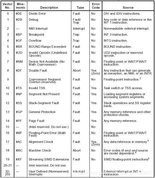
The interrupt vector table is located in the first 1024 bytes of memory at addresses 000000H–0003FFH. It contains 256 different four-byte interrupt vectors.An interrupt vector contains the address (segment and offset) of the interrupt service procedure.
The x86 allows up to 256 different interrupt or exception entry points into the kernel, each with a different interrupt vector. A vector is a number between 0 and 255. An interrupt’s vector is determined by the source of the interrupt: different devices, error conditions, and application requests to the kernel generate interrupts with different vectors.
- 范围[0,31]内的32个向量被Exception和NMI使用,但当前并非所有这32个向量都已经被使用,有几个当前没有被使用的,你也不要擅自使用它们,它们被保留,以备将来可能增加新的Exception。
- 范围[32,255]内的向量被保留给用户定义的Interrupts。Intel没有定义,也没有保留这些Interrupts。用户可以将它们用作外部I/O设备中断(8259A IRQ),或者System Call (Software Interrupts)等。
向量表如下所示:
Memory address:

refer to
aarch64_exception_and_interrupt_handling.pdf