E F M 3 2 - G 2 X X - D K 开 发 板 电路图
本文介绍了EFM32 Gecko系列主要特性,方框图和EFM32-G2XX-DK开发板主要特性与详细的电路图.
低功耗微控制器(Energy Micro)公司的32位处理器EFM32 Gecko系列产品采用ARM Cortex-M3内核,工作频率高达32MHz.系列产品具有低电流特性,配合2µs的唤醒时间,使其至少增加了4倍的电池使用寿命。启动模式下从闪存FLASH执行代码所消耗的典型电流为160µA/MHz、深度睡眠模式和关断模式下分别为900nA和20nA。主要用在不断发展的智能仪表市场和对功耗敏感的应用,如楼宇自动化、安防系统和便携式健康医疗及健身设备。本文介绍了EFM32 Gecko系列主要特性,方框图和EFM32-G2XX-DK开发板主要特性与详细的电路图.
The EFM32 MCUs are the world’s most energy friendly microcontrollers. With a unique combination of the powerful 32-bit ARM Cortex-M3, innovative low energy techniques, short wake-up time from energy saving modes, and a wide selection of peripherals, the EFM32G microcontroller is well suited for any battery operated application as well as other systems requiring high performance and low-energy consumption.
This section gives a short introduction to each of the modules in general terms and also and shows a summary of the configuration for the EFM32G232 devices.
The ARM Cortex-M3 includes a 32-bit RISC processor which can achieve as much as 1.25 Dhrystone MIPS/MHz. A Memory Protection Unit with support for up to 8 memory segments is included, as well as a Wake-up Interrupt Controller handling interrupts triggered while the CPU is asleep.
EFM32 Gecko系列主要特性:
• ARM Cortex-M3 CPU platform
• High Performance 32-bit processor @ up to 32 MHz
• Memory Protection Unit
• Wake-up Interrupt Controller
• Flexible Energy Management System
• 20 nA @ 3 V Shutoff Mode
• 0.6 μA @ 3 V Stop Mode, including Power-on Reset, Brown-out Detector, RAM and CPU retention
• 0.9 μA @ 3 V Deep Sleep Mode, including RTC with 32.768 kHz oscillator, Power-on Reset, Brown-out Detector, RAM and CPU retention
• 45 μA/MHz @ 3 V Sleep Mode
• 180 μA/MHz @ 3 V Run Mode, with code executed from flash
• 128/64/32 KB Flash
• 16/16/8 KB RAM
• 53 General Purpose I/O pins
• Configurable Push-pull, Open-drain, pull-up/down, input filter, drive strength
• Configurable peripheral I/O locations
• 16 asynchronous external interrupts
• 8 Channel DMA Controller
• 8 Channel Peripheral Reflex System for autonomous inter-peripheral signaling
• Hardware AES with 128/256-bit keys in 54/75 cycles
• Timers/Counters
• 3× 16-bit Timer/Counter
• 3×3 Compare/Capture/PWM channels
• Dead-Time Insertion on TIMER0
• 16-bit Low Energy Timer
• 24-bit Real-Time Counter
• 3× 8-bit Pulse Counter
• Watchdog Timer with dedicated RC oscillator @ 50 nA
• Communication interfaces
• 3× Universal Synchronous/Asynchronous Receiver/Transmitter
• UART/SPI/SmartCard (ISO 7816)/IrDA
• Triple buffered full/half-duplex operation
• 2× Low Energy UART
• Autonomous operation with DMA in Deep Sleep Mode
• I2C Interface with SMBus support
• Address recognition in Stop Mode
• Ultra low power precision analog peripherals
• 12-bit 1 Msamples/s Analog to Digital Converter
• 8 single ended channels/2 differential channels
• On-chip temperature sensor
• Conversion tailgating for predictable latency
• 12-bit 500 ksamples/s Digital to Analog Converter
• 2× Analog Comparator
• Capacitive sensing with up to 16 inputs
• Supply Voltage Comparator
• Ultra efficient Power-on Reset and Brown-Out Detector
• Pre-Programmed Serial Bootloader
• Temperature range -40 to 85 ºC
• Single power supply 1.8 to 3.8 V
• LQFP64 package

图1. EFM32 Gecko系列方框图
EFM32-G2XX-DK开发板
The EFM32-G2XX-DK is a highly flexible development kit. It offers many features and peripherals to the EFM32 through jumperless configuration. The different features on the kit are available as configured in the motherboard’s Board Controller. Configuration is easily done by a simple API in the kit Board Support Package.
If none of the motherboard features are needed, configuration of the Board Controller is not necessary.
All EFM32 GPIO pins are available on the prototyping board.
EFM32-G2XX-DK开发板主要特性:
• Advanced Energy Monitoring system for precise current tracking.
• Special hardware configuration for isolation of the MCU power domain.
• Replaceable prototyping board for quick custom application development.
• Full feature USB debugger / emulator with debug out functionality.
• 3.5-inch TFT-LCD 320x240 pixel RGB color display.
• Board Controller for board configuration / signal routing.
• Single ended and differential ADC inputs.
• Line-in stereo audio input amplifier.
• Line-out stereo audio output amplifier.
• 2 RS232 connectors.
• 3-axis accelerometer.
• SPI Flash and microSD card reader (SPI mode).
• EEPROM.
• Temperature sensor.
• IrDA tranceiver.
• 256Kx16bit / 512KB parallel bus SRAM.
• 2Mx16 / 4MB parallel bus NOR Flash.
• Ambient light sensor and potmeter.
• 5 way joystick.
• 4 User buttons, 8-bit DIP switch and 16 user LEDs.

图2.EFM32-G2XX-DK开发板外形图
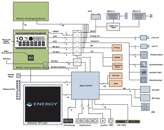
图3.EFM32-G2XX-DK开发板方框图

图4.EFM32-G2XX-DK开发板电路图(1)

图5.EFM32-G2XX-DK开发板电路图(2)

图6.EFM32-G2XX-DK开发板电路图(3)

图7.EFM32-G2XX-DK开发板电路图(4)
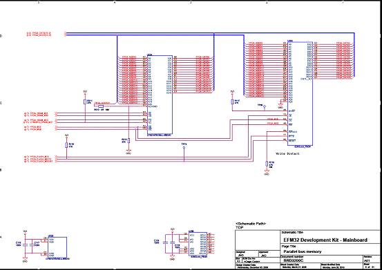
图8.EFM32-G2XX-DK开发板电路图(5)

图9.EFM32-G2XX-DK开发板电路图(6)
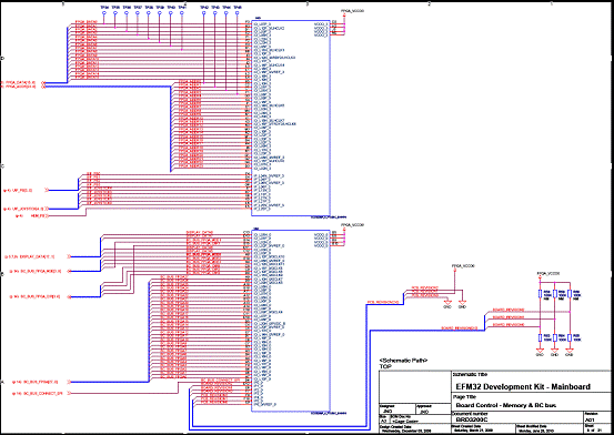
图10.EFM32-G2XX-DK开发板电路图(7)
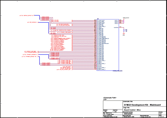
图11.EFM32-G2XX-DK开发板电路图(8)
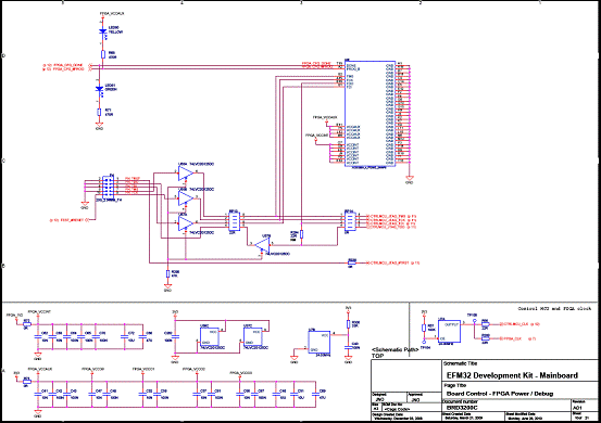
图12.EFM32-G2XX-DK开发板电路图(9)
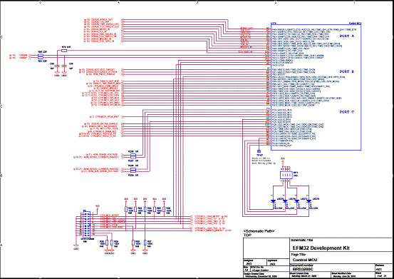
图13.EFM32-G2XX-DK开发板电路图(10)

图14.EFM32-G2XX-DK开发板电路图(11)

图15.EFM32-G2XX-DK开发板电路图(12)

图16.EFM32-G2XX-DK开发板电路图(13)
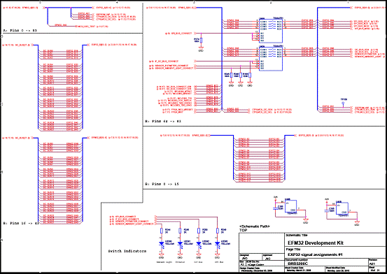
图17.EFM32-G2XX-DK开发板电路图(14)
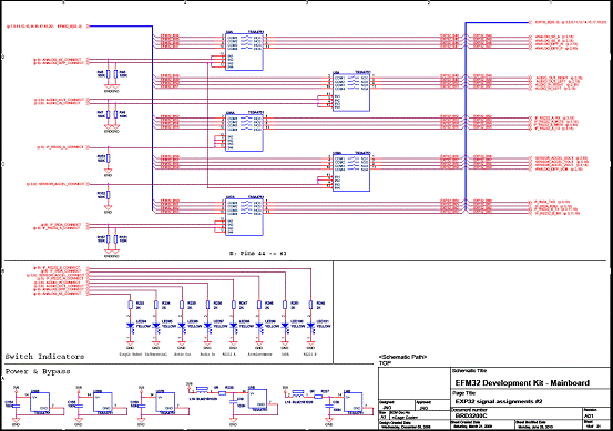
图18.EFM32-G2XX-DK开发板电路图(15)
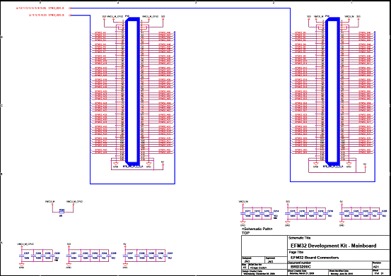
图19.EFM32-G2XX-DK开发板电路图(16)
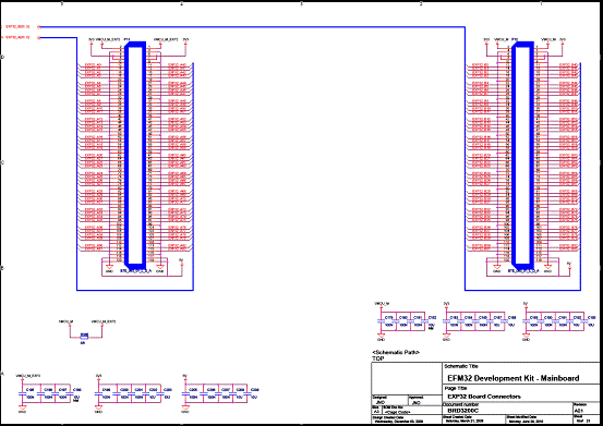
图20.EFM32-G2XX-DK开发板电路图(17)

图21.EFM32-G2XX-DK开发板电路图(18)
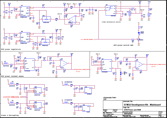
图22.EFM32-G2XX-DK开发板电路图(19)
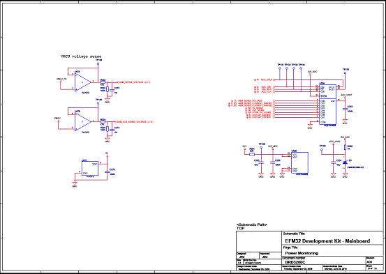
图23.EFM32-G2XX-DK开发板电路图(20)