串口到DMA
—————目录—————
一、通信的一些基本概念理解
二、串口通信协议简介
三、功能框图理解
四、stm32与上位机通信
五、DMA
————————————
对应课程
野火 第21节USART
https://i.youku.com/firege
一、通信的一些基本概念理解
1. 串行与并行通信
【1】并行通信定义:
在计算机和终端之间的数据传输通常是靠电缆或信道上的电流或电压变化【脉冲信号】实现的。如果一组数据的各数据位在多条线上同时被传输,这种传输方式称为并行通信。
【2】串行更常见:
并行数据传输只适用于近距离的通信,通常传输距离小于30米。且串行简单,传输只用一根线,更新迭代更快。
2. 全双工、半双工、单工
【1】区分:
全双工:可以同时互传
半双工:可以分时互传
单工:单向传输
【2】半双工用的最多
3. 同步与异步
【1】区分:
同步:同步双方的时钟误差需较小。传输数据大多数为有效数据
异步:在有效数据中插入各种标识符,暗示开始、结束、校验。
4. 通信的速率【比特率与波特率】
【1】区分
比特率:每秒钟传输的二进制位数,单位为比特每秒(bit/s)
波特率:没秒钟传输的码元个数
码元:码元是在信道中最小的一个脉冲单位。
【2】码元
二进制码元:0、1
四进制码元:00、01、10、11
八进制码元:000、001、010、011、100、101、110、111
【3】联系
当且仅当码元为二进制码元时,波特率和比特率等价。
二、串口通信协议简介
1. 物理层【硬件层】
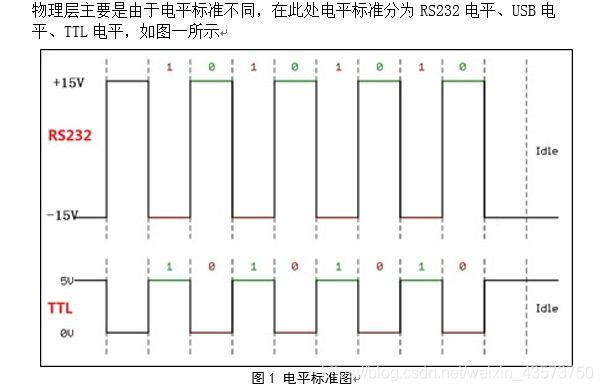
TTL电平:从单片机、芯片出来的电平都叫TTL电平。其中STM32的高电平为3.3V,51单片机的高电平为5V。
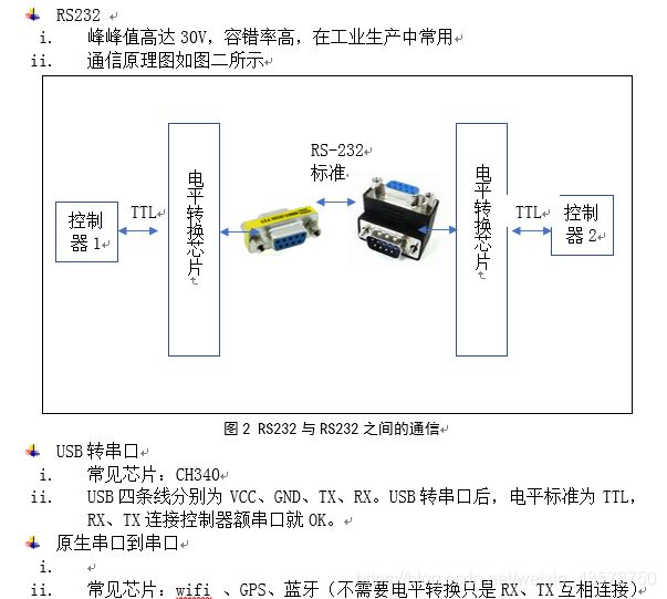
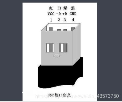
USB内部构造图,两边的是USB电平,中间是数据
2.协议层【软件层】
【1】数据包的组成如图三

【2】校验方式
、奇校验:1的和为奇数
、偶校验:1的和为偶数
、0校验:校验位恒为0
、1校验:校验位恒为1
三、功能框图理解
1.串口的引脚
接口通过三个引脚与其他设备连接在一起.任何USART双向通信至少需要两个引脚,RX、TX
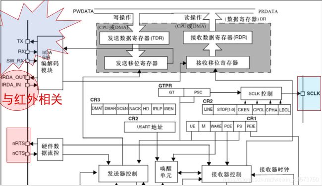

【1】USART和UART相差了个S,S 叫做 synchronous(同步)
——USART : 通用同步/异步串行接收/发送器
(Universal Synchronous/Asynchronous Receiver/Transmitter)
——UART : 通用异步收发传输器(Universal Asynchronous Receiver/Transmitter)
【2】重点:会找引脚

2.波特率
【1】基本概念:表示每秒钟发送的码元个数;在串口里面,波特率刚好等于比特率。
【2】算波特率:
(1)涉及到寄存器USART_BRR(波特率寄存器)
(2)串口1是在APB2总线上,其他串口是在APB1总线上,在写程序的时候注意要切换时钟

3.寄存器简介
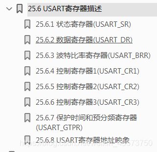
【1】状态寄存器 SR(Status register)

【2】数据寄存器 DR (Data Register)

【3】波特率寄存器 BRR ()
【4】控制寄存器1 CR1(Control Register)

【5】控制寄存器2 CR2

【6】控制寄存器3 CR3
【7】保护时间和预分频寄存器 GTPR
4.数据的发送、数据接收的流程
【1】初始化
串口初始化
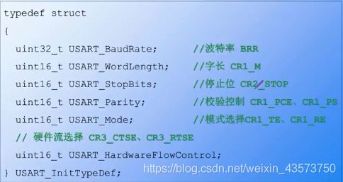
在项目开发过程中,异步串口使用比较多。串口的每个数据帧格式如下:

字长通常为8个数据位

停止位通常为1个停止位

步骤:打开校验使能 ->选择校验方式 ->校验出错中断使能
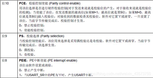
当PE == 1 时,奇偶校验产生错误

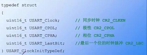
同步时钟:同步时钟初始化
【2】数据发送、接收过程
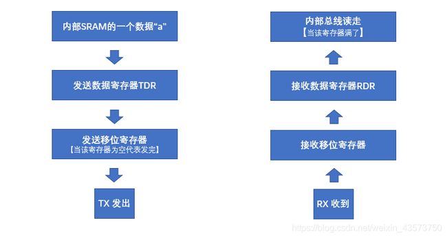 (1) 发送 总体共二步:
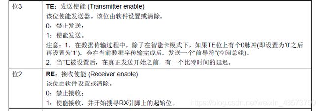
第一步:把UE = 1,TE = 1 、RE = 1 .
第二步:TXE = 1 , TC = 1 <发送寄存器为为空,发送完成>
附:
a. TXE: TX empty;TC: transmission complete
b.发送一个字节可以只判断TXE,发送多个字节必须判断TC
c. TXE = 1 : 发送数据寄存器的数据全部发送到发送移位寄存器中了.
d. TC = 1 : 发送移位寄存器为空,数据全部发送到TX处,发送完成。
e. 他们相应的中断位分别为TXEIE、TCIE
(2)接收 总体二步
第一步:UE = 1; TE = 1 ;RE = 1;
第二步:RXNE = 1;<接收数据寄存器为空,接收完毕>
附:
a. RXNE 即为 RX not empty.
b. 接收 只能判断一个,RXNE.
c.对应中断 RXNEIE



四、stm32与上位机通信
1、printf函数可以发给上位机,这需要fputc函数、fgetc函数来帮忙,放到usart.c里面
///重定向c库函数printf到串口,重定向后可使用printf函数
int fputc(int ch, FILE *f)
{
		/* 发送一个字节数据到串口 */
		USART_SendData(DEBUG_USARTx, (uint8_t) ch);

		/* 等待发送完毕 */
		while (USART_GetFlagStatus(DEBUG_USARTx, USART_FLAG_TXE) == RESET);

		return (ch);
}

///重定向c库函数scanf到串口,重写向后可使用scanf、getchar等函数
int fgetc(FILE *f)
{
		/* 等待串口输入数据 */
		while (USART_GetFlagStatus(DEBUG_USARTx, USART_FLAG_RXNE) == RESET);

		return (int)USART_ReceiveData(DEBUG_USARTx);
}
- 串口1~5 分别定义五种宏定义
/**
  * 串口宏定义,不同的串口挂载的总线和IO不一样,移植时需要修改这几个宏
  */

#define DEBUG_USART1 0
#define DEBUG_USART2 0
#define DEBUG_USART3 0
#define DEBUG_USART4 0
#define DEBUG_USART5 1

#if  DEBUG_USART1
// 串口1-USART1
#define  DEBUG_USARTx                   USART1
#define  DEBUG_USART_CLK                RCC_APB2Periph_USART1
#define  DEBUG_USART_APBxClkCmd         RCC_APB2PeriphClockCmd
#define  DEBUG_USART_BAUDRATE           115200

// USART GPIO 引脚宏定义
#define  DEBUG_USART_GPIO_CLK           (RCC_APB2Periph_GPIOA)
#define  DEBUG_USART_GPIO_APBxClkCmd    RCC_APB2PeriphClockCmd

#define  DEBUG_USART_TX_GPIO_PORT         GPIOA
#define  DEBUG_USART_TX_GPIO_PIN          GPIO_Pin_9
#define  DEBUG_USART_RX_GPIO_PORT       GPIOA
#define  DEBUG_USART_RX_GPIO_PIN        GPIO_Pin_10

#define  DEBUG_USART_IRQ                USART1_IRQn
#define  DEBUG_USART_IRQHandler         USART1_IRQHandler


#elif DEBUG_USART2
// 串口2-USART2
#define  DEBUG_USARTx                   USART2
#define  DEBUG_USART_CLK                RCC_APB1Periph_USART2
#define  DEBUG_USART_APBxClkCmd         RCC_APB1PeriphClockCmd
#define  DEBUG_USART_BAUDRATE           115200

// USART GPIO 引脚宏定义
#define  DEBUG_USART_GPIO_CLK           (RCC_APB2Periph_GPIOA)
#define  DEBUG_USART_GPIO_APBxClkCmd    RCC_APB2PeriphClockCmd

#define  DEBUG_USART_TX_GPIO_PORT         GPIOA
#define  DEBUG_USART_TX_GPIO_PIN          GPIO_Pin_2
#define  DEBUG_USART_RX_GPIO_PORT       GPIOA
#define  DEBUG_USART_RX_GPIO_PIN        GPIO_Pin_3

#define  DEBUG_USART_IRQ                USART2_IRQn
#define  DEBUG_USART_IRQHandler         USART2_IRQHandler

#elif DEBUG_USART3
//// 串口3-USART3
#define  DEBUG_USARTx                   USART3
#define  DEBUG_USART_CLK                RCC_APB1Periph_USART3
#define  DEBUG_USART_APBxClkCmd         RCC_APB1PeriphClockCmd
#define  DEBUG_USART_BAUDRATE           115200

// USART GPIO 引脚宏定义
#define  DEBUG_USART_GPIO_CLK           (RCC_APB2Periph_GPIOB)
#define  DEBUG_USART_GPIO_APBxClkCmd    RCC_APB2PeriphClockCmd

#define  DEBUG_USART_TX_GPIO_PORT         GPIOB
#define  DEBUG_USART_TX_GPIO_PIN          GPIO_Pin_10
#define  DEBUG_USART_RX_GPIO_PORT       GPIOB
#define  DEBUG_USART_RX_GPIO_PIN        GPIO_Pin_11

#define  DEBUG_USART_IRQ                USART3_IRQn
#define  DEBUG_USART_IRQHandler         USART3_IRQHandler

#elif DEBUG_USART4
// 串口4-UART4
#define  DEBUG_USARTx                   UART4
#define  DEBUG_USART_CLK                RCC_APB1Periph_UART4
#define  DEBUG_USART_APBxClkCmd         RCC_APB1PeriphClockCmd
#define  DEBUG_USART_BAUDRATE           115200

// USART GPIO 引脚宏定义
#define  DEBUG_USART_GPIO_CLK           (RCC_APB2Periph_GPIOC)
#define  DEBUG_USART_GPIO_APBxClkCmd    RCC_APB2PeriphClockCmd

#define  DEBUG_USART_TX_GPIO_PORT         GPIOC
#define  DEBUG_USART_TX_GPIO_PIN          GPIO_Pin_10
#define  DEBUG_USART_RX_GPIO_PORT       GPIOC
#define  DEBUG_USART_RX_GPIO_PIN        GPIO_Pin_11

#define  DEBUG_USART_IRQ                UART4_IRQn
#define  DEBUG_USART_IRQHandler         UART4_IRQHandler

#elif DEBUG_USART5
// 串口5-UART5
#define  DEBUG_USARTx                   UART5
#define  DEBUG_USART_CLK                RCC_APB1Periph_UART5
#define  DEBUG_USART_APBxClkCmd         RCC_APB1PeriphClockCmd
#define  DEBUG_USART_BAUDRATE           115200

// USART GPIO 引脚宏定义
#define  DEBUG_USART_GPIO_CLK           (RCC_APB2Periph_GPIOC|RCC_APB2Periph_GPIOD)
#define  DEBUG_USART_GPIO_APBxClkCmd    RCC_APB2PeriphClockCmd

#define  DEBUG_USART_TX_GPIO_PORT         GPIOC
#define  DEBUG_USART_TX_GPIO_PIN          GPIO_Pin_12
#define  DEBUG_USART_RX_GPIO_PORT       GPIOD
#define  DEBUG_USART_RX_GPIO_PIN        GPIO_Pin_2

#define  DEBUG_USART_IRQ                UART5_IRQn
#define  DEBUG_USART_IRQHandler         UART5_IRQHandler

#endif
五、DMA
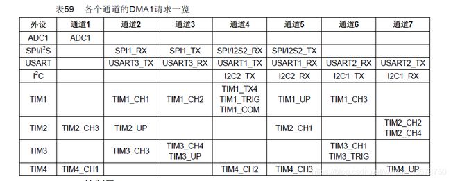
1、DMA有三种方式 M-M, P-M, M-P
M-M任何通道都可以用, P-M, M-P需要遵循下表
2.仲裁
软件仲裁 :CCR寄存器

硬件仲裁 :
通道1 > 通道2 > 通道3 > 通道4 > 通道5 > 通道6 > 通道7
DMA1 > DMA2
3.结构体
typedef struct
{
  uint32_t DMA_PeripheralBaseAddr; /*!< Specifies the peripheral base address for DMAy Channelx. */

  uint32_t DMA_MemoryBaseAddr;     /*!< Specifies the memory base address for DMAy Channelx. */

  uint32_t DMA_DIR;                /*!< Specifies if the peripheral is the source or destination.
                                        This parameter can be a value of @ref DMA_data_transfer_direction */

  uint32_t DMA_BufferSize;         /*!< Specifies the buffer size, in data unit, of the specified Channel.
                                        The data unit is equal to the configuration set in DMA_PeripheralDataSize
                                        or DMA_MemoryDataSize members depending in the transfer direction. */

  uint32_t DMA_PeripheralInc;      /*!< Specifies whether the Peripheral address register is incremented or not.
                                        This parameter can be a value of @ref DMA_peripheral_incremented_mode */

  uint32_t DMA_MemoryInc;          /*!< Specifies whether the memory address register is incremented or not.
                                        This parameter can be a value of @ref DMA_memory_incremented_mode */

  uint32_t DMA_PeripheralDataSize; /*!< Specifies the Peripheral data width.
                                        This parameter can be a value of @ref DMA_peripheral_data_size */

  uint32_t DMA_MemoryDataSize;     /*!< Specifies the Memory data width.
                                        This parameter can be a value of @ref DMA_memory_data_size */

  uint32_t DMA_Mode;               /*!< Specifies the operation mode of the DMAy Channelx.
                                        This parameter can be a value of @ref DMA_circular_normal_mode.
                                        @note: The circular buffer mode cannot be used if the memory-to-memory
                                              data transfer is configured on the selected Channel */

  uint32_t DMA_Priority;           /*!< Specifies the software priority for the DMAy Channelx.
                                        This parameter can be a value of @ref DMA_priority_level */

  uint32_t DMA_M2M;                /*!< Specifies if the DMAy Channelx will be used in memory-to-memory transfer.
                                        This parameter can be a value of @ref DMA_memory_to_memory */
}DMA_InitTypeDef;
4. M -> P 编程要点
初始化串口
配置DMA初始化结构体
编写主函数(开启串口发送DMA请求)
 /* 初始化USART */
  USART_Config();

  /* 配置使用DMA模式 */
  USARTx_DMA_Config();

 /* USART1 向 DMA发出TX请求 */
  USART_DMACmd(DEBUG_USARTx, USART_DMAReq_Tx, ENABLE);