实验篇---MPLS v+p+n + OSPF sham-link
实验拓扑图:
实验要求:
1.如图连接拓扑,合理规划IP地址,各自创建一个环回 ;
2.AS 100内使用IGP协议为OSPF ,如图运行动态路由协议 ;
3.要求R1-R5之间启用MPLS VPN ; R6-R7之间启用MPLS VPN ;
4.将两条VPN 进行合并 ;
5.R6-R7之间使用OSPF协议,要求R6-R7之间的私有IP地址通信优先使用MPLS,R6-R7之间的直连为备份。
解题思路及步骤:
第一步:完成基础的接口IP地址
R1:
Loopback0 :1.1.1.1 24
g0/0/0:12.1.1.1 24
R2:
Loopback0 :2.2.2.2 32
g0/0/0:23.1.1.1 24
g0/0/1:12.1.1.2 24
g0/0/2:26.1.1.1 24
R3:
Loopback0 :3.3.3.3 32
g0/0/0:34.1.1.1 24
g0/0/1:23.1.1.2 24
R4:
Loopback0 :4.4.4.4 32
g0/0/0:45.1.1.1 24
g0/0/1:34.1.1.2 24
g0/0/2:47.1.1.1 24
R5:
Loopback0 :5.5.5.5 24
g0/0/0:45.1.1.2 24
R6:
Loopback0 :6.6.6.6 24
g0/0/2:26.1.1.2 24
R7:
Loopback0 :7.7.7.7 24
g0/0/2:47.1.1.2 24
第二步:在MPLS区域启用OSPF 100动态路由协议
R2:
ospf 100 router-id 2.2.2.2
 area 0.0.0.0
  network 2.2.2.2 0.0.0.0
  network 23.1.1.1 0.0.0.0
interface LoopBack0
 ip address 2.2.2.2 255.255.255.255
 ospf network-type broadcast

R3:
ospf 100 router-id 3.3.3.3
 area 0.0.0.0
  network 3.3.3.3 0.0.0.0
  network 23.1.1.2 0.0.0.0
  network 34.1.1.1 0.0.0.0
interface LoopBack0
 ip address 3.3.3.3 255.255.255.255
 ospf network-type broadcast

R4:
ospf 100 router-id 4.4.4.4
 area 0.0.0.0
  network 4.4.4.4 0.0.0.0
  network 34.1.1.2 0.0.0.0
interface LoopBack0
 ip address 4.4.4.4 255.255.255.255
 ospf network-type broadcast
第三步:在MPLS区域R2与R4建立BGP邻居关系(两个PE端建立BGP邻居)
R2:
bgp 100
 router-id 2.2.2.2
 peer 4.4.4.4 as-number 100
 peer 4.4.4.4 connect-interface LoopBack0
R4:
bgp 100
 router-id 4.4.4.4
 peer 2.2.2.2 as-number 100
 peer 2.2.2.2 connect-interface LoopBack0
第四步:启用RIP的R1与R5之间实现通信
1、在R1与R5上启用RIP
R1:
rip 100
 version 2
 network 1.0.0.0
 network 12.0.0.0
R5:
rip 200
 version 2
 network 5.0.0.0
 network 45.0.0.0
2、PE端创建VRF
R2与R4同:
ip -instance hcip
 ipv4-family
  route-distinguisher 1:1
  -target 10:10 export-extcommunity
  -target 10:10 import-extcommunity
3、进入接口将接口划入ARF中并重新配置该接口的IP地址
4、在PE端运行RIP
5、PE端之间激活VPNV4-BGP能力并开启传递RT参数功能
6、在ISP(R2-R3-R4)区域启用MPLS
查看命令:
display mpls ldp peer —查看MPLS LDP会话关系
display mpls ldp lsp —查看LIB表
display mpls lsp —查看LSP(LFIB)
R2:
mpls lsr-id 2.2.2.2     ---配置MPLS LSR-ID(该地址必须可达)
mpls                    ---开启MPLS功能
 lsp-trigger all        ---开启针对其他路由器分配标签(在egress设备上),这条命令的原因:默认情况下,MPLS仅仅针对主机分配标签
mpls ldp                ---开启支持MPLS LDP功能

在MPLS域内的接口开启MPLS以及MPLS LDP功能:

interface GigabitEthernet0/0/0
 ip address 23.1.1.1 255.255.255.0
 mpls
 mpls ldp
R3:
mpls lsr-id 3.3.3.3
mpls
mpls ldp
 lsp-trigger all

interface GigabitEthernet0/0/0
 ip address 34.1.1.1 255.255.255.0
 mpls
 mpls ldp

interface GigabitEthernet0/0/1
 ip address 23.1.1.2 255.255.255.0
 mpls
 mpls ldp
R4:
mpls lsr-id 4.4.4.4
mpls
mpls ldp
 lsp-trigger all

interface GigabitEthernet0/0/1
 ip address 34.1.1.2 255.255.255.0
 mpls
 mpls ldp
7、将PE端VRF中的路由重发布到VPN-instance hcip中
R2:
ipv4-family -instance hcip
  import-route rip 100
R4:
ipv4-family -instance hcip
  import-route rip 200
查看学到的路由:
display bgp v4 -instance hcip routing-table
8、将PE端VRF中BGP的路由重发布到VRF的IGP(RIP)协议中
R2:
rip 100 -instance hcip
 import-route bgp
R4:
rip 200 -instance hcip
 import-route bgp
查看PE端路由学习命令:
display ip routing-table -instance hcip
查看CE端学习到的路由:
display ip routing-table protocol rip
9、R1-R5测试(ping)结果
第五步:启用OSPF的R6与R7之间实现通信
与第四步思路相同:
1、在R6与R7上启用OSPF
R6:
ospf 200 router-id 6.6.6.6
 area 0.0.0.0
  network 6.6.6.6 0.0.0.0
  network 26.1.1.2 0.0.0.0

R7:
ospf 200 router-id 7.7.7.7
 area 0.0.0.0
  network 7.7.7.7 0.0.0.0
  network 47.1.1.2 0.0.0.0
2、在PE端创建VRF
R2与R4同:
ip -instance hcia
 ipv4-family
  route-distinguisher 2:2
  -target 100:100 export-extcommunity
  -target 100:100 import-extcommunity
3、进入接口将接口划入ARF中并重新配置该接口的IP地址
R2:
interface GigabitEthernet0/0/2
 ip binding -instance hcia
 ip address 26.1.1.1 255.255.255.0
R4:
interface GigabitEthernet0/0/2
 ip binding -instance hcia
 ip address 47.1.1.1 255.255.255.0
4、在PE端运行OSPF
R2:
ospf 200 router-id 22.2.2.2 -instance hcia
 area 0.0.0.0
  network 26.1.1.1 0.0.0.0
R4:
ospf 200 router-id 44.4.4.4 -instance hcia
 area 0.0.0.0
  network 47.1.1.1 0.0.0.0
5、将PE端VRF中的路由重发布到VPN-instance hcia中
R2与R4同:
ipv4-family -instance hcia
  import-route ospf 200
6、将PE端VRF中BGP的路由重发布到VRF的IGP(OSPF 200)协议中
R2:
ospf 200 router-id 22.2.2.2 -instance hcia
 import-route bgp
R4:
ospf 200 router-id 44.4.4.4 -instance hcia
 import-route bgp
7、R6-R7测试(ping)结果
第六步:将 R1-R5 和 R6-R7 两条VPN进行合并
1、OSPF 200与RIP 100/200互相通信,在两个PE端都将100:100打入进VPN-instance hcip中(或者将10:10打入进VPN-instance hcia 中):
R2与R4同:
ip -instance hcip
 ipv4-family
  route-distinguisher 1:1
  -target 10:10 100:100 export-extcommunity
  -target 10:10 100:100 import-extcommunity
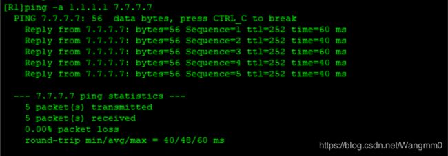
2、OSPF 200与RIP 100/200互相通信测试结果:
第七步:现在需要在R6 R7之间拉一条专线,用来备份以防ISP线路故障
我们需要用到sham-link技术将R6R7的AREA0区域连起来,让R6到R7通过1类lsa学习路由,然后在通过修改开销值的方法让R6访问R7数据走R2-R4
1、将R6和R7直连,配置IP地址并将此接口通告进area 0中
R6:
interface GigabitEthernet0/0/0
 ip address 67.1.1.1 255.255.255.0
 ospf enable 200 area 0.0.0.0
R7:
interface GigabitEthernet0/0/0
 ip address 67.1.1.2 255.255.255.0
 ospf enable 200 area 0.0.0.0
2.在R2和R4上创建环回接口1 将其划入VRF中
R2:
interface LoopBack1
 ip binding -instance hcia
 ip address 10.1.1.1 255.255.255.255
R4:
interface LoopBack1
 ip binding -instance hcia
 ip address 10.1.1.2 255.255.255.255
3.在R2和R4上,将环回1宣告进BGP中
R2:
ipv4-family -instance hcia
  network 10.1.1.1 255.255.255.255
  import-route ospf 200
R4:
ipv4-family -instance hcia
  network 10.1.1.2 255.255.255.255
  import-route ospf 200
此时我们可以发现R2的环回1可以ping通R4的环回1,因为ISP中间是通过标签的方式通讯的 所以可以ping通:

4.在R2和R4的OSPF 200 area 0上启用sham-link
R2:
ospf 200 router-id 22.2.2.2 -instance hcia
 area 0.0.0.0
  sham-link 10.1.1.1 10.1.1.2
R4:
ospf 200 router-id 44.4.4.4 -instance hcia
 area 0.0.0.0
  sham-link 10.1.1.2 10.1.1.1
5.进入R6和R7接口g0/0/0修改OSPF cost值为5 (大于3即可),让R6访问R7数据走R2-R4
R6:
interface GigabitEthernet0/0/0
 ospf cost 5
R7:
interface GigabitEthernet0/0/0
 ospf cost 5
6.查看R6访问R7的下一跳:
下一跳为26.1.1.1(R2与R6的直连端口IP地址),则实验成功!


