Veristand学习札记(2)-工程介绍
1 Veristand项目
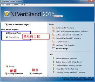
打开Veristand软件,三个重要的部分如下:
图1 Veristand软件
“配置”默认的工程。
图2 一个工程
1.1 工程存储路劲
自带范例的默认存储路径在C:\Users\Public\Documents\NationalInstruments\NI VeriStand 2015\Projects\Example
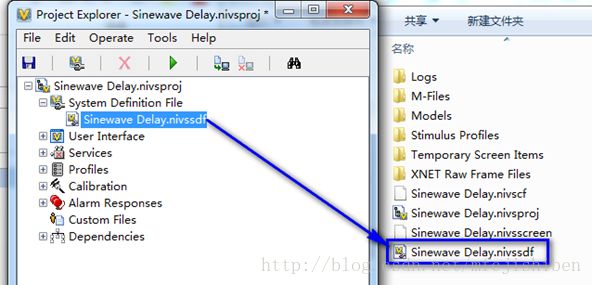
图3 SDF文件
其中,SystemDefineFile就是传说中的SDF文件。顾名思义,其定义了系统的一些参数,具体哪些参数?双击或右键-Launch System Explore进入查看。
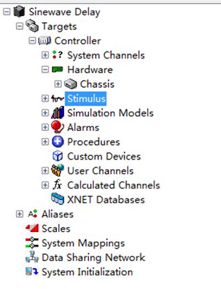
图4 SDF配置
各部分的功能在点击后都有解释。
1.2 Target下Controller参数设置
Target指的是仿真模型运行的平台。Controller中设置了运行平台的系统,是普通的Windows还是实时的Pharlap(PXI机箱实时系统)、Vxworks或者Linux。此时需注意,不同的平台或者叫操作系统下面的设备驱动是不一样的。
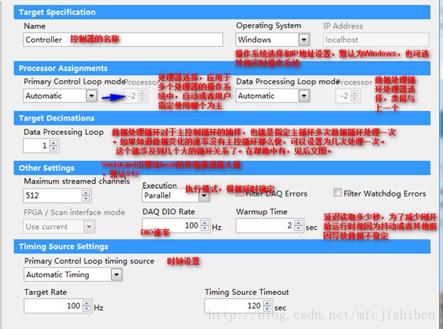
各个参数大概意义如下:
图5 Target参数
以上详细参见帮助文档中【ControllerConfiguration Page】章节。
关于执行模式的详细解释摘录如下:
o Executionmode执行模式设置—Specifiesthe execution mode for the loops of the VeriStand Engine. You can select fromthe following options:
- Parallel—(Default默认是并行执行) Executes all the loops of the VeriStand Engine in parallel所有循环都是并行. In this mode, the system only writes values to and initiates execution of the Model Execution Loop(s) on the first iteration of the system, but it does not read values from the loop(s)这个模式下,系统在第一个循环时候只写数据并初始化模型执行循环但是不读取数据. On the second and subsequent iterations, the system reads values from the previous execution of the Model Execution Loop(s).第二次循环是才从模型循环中读数据,这样提高整个系统的执行速度,尤其是在多核目标时候。 This causes a one-cycle delay on executing your model(s), but can increase the execution speed of the entire system, especially on multi-core targets.
· LowLatency低延迟—Executes all the loops of the VeriStandEngine in parallel, but writes values to, executes, and reads values from theModel Execution Loop(s) at every iteration of the system, including the first.National Instruments recommends you select this mode only if you need tominimize the latency between your inputs, model execution, and outputs. Waitingfor the Model Execution Loop(s) to read, execute, and write on each iterationcan significantly slow the execution speed of the system. 只有需要最小延迟的时候才选择这个模式,模型循环读写操作会明显降低系统在每个循环过程中的执行速度。
1.3 System Channels
列出了系统中的通道。这些通道是哪儿来的呢?是与工程中选定的设备的输入输出参数有关的,用户管理系统设置,类似于全局变量。
1.4 Hardware
Hardware contains any hardware chassis youadd. Hardware chassis can contain NI-DAQ devices, NI FPGA targets, reflectivememory devices, NI-XNET devices, and timing and sync devices.To add any third-partyhardware devices, you must use custom devices.这个项目下面值列出了NI支持的本厂家的DAQ设备、FPGA设备、X-NET设备、反射内存卡和定时同步设备。要是第三方的,需要用CD。其实,CD只是在不是NI厂家的板卡时,根据Veristand指定的规则来封装的一个自定义设备。
1.5 Hardware-增加一个NI板卡
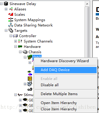
在DAQ上右键-Add DAQ Device。
图6 增加DAQ-1
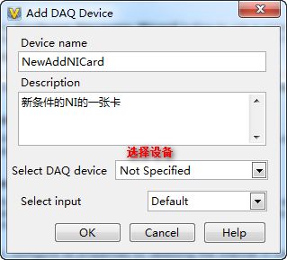
图7 设置新增加的板卡
在DAQ Device中选择一张卡,以PCI-6704为例。
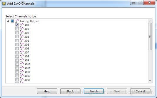
图8 选择AO通道
选择AO通道,同时设置通道的属性,完成后点击Next,选择要使用哪个物理通道。暂时以AO0为例子,Finish。
图9 选择通道
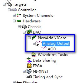
完成后,在DAQDevice下面,就会出现新设置的板卡资源。
图10 新添加的板卡资源
1.6 Stimulus激励设备
设定激励源。这些设置在哪儿实现?有何意义?Step是干啥用的。
图11 Stimulus设置
通过映射关系绑定到某个设备的输出引脚上,作为激励输出。区别于板卡数据输出,这个可以配置输出时间和次数。更偏向于电源、触发等之类的控制(个人理解)。
1.7 CustomDevice
这个自定义设备是并列与DAQ设备而言的。右键可选择添加一个CD。但是问题是,CD怎么来的?
