8 zedboard Data Logging using SD Cards
Data Logging using SD Cards
In this lab, All non-volatile memories available on the Zedboard are studied. The main focus is on the SD memory, its controller (SD/SDIO), and its driver. An application is developed to use the SD card to store a string of characters in the format “HH:MM:SS Event: Sensor X Triggered #” every time the lower push button on the Zedboard is pressed (the push button here emulates a sensor in a real life situation). HH:MM:SS represents the real time. The FatFs (File allocation table File system) APIs are used by the application to access the SD card.

Lab7 Design Flow

Lab7 Block Diagram

Lab7 Board Interface
Data logging in embedded systems is the activity of saving some data on a non-volatile memory. The data could be anything, to list few: sensors readings such as ambient temperature; figures relate to operation, for instance, energy consumption.
There are two non-volatile memories available on the Zedboard that can be used for the purpose of data logging. The first one is the QSPI (quad-SPI) serial NOR flash with a capacity of 256Mbit. The second is the SD card accessed through the SD card connector available on the back of the Zedboard (A 4GB SD card is already inserted in the connector).

Zedboard Block Diagram
Both of these memories could be used for initialization, or data storage. By initialization, we mean it can be used to initialize the PS subsystem as well as to configure the PL subsystem on boot up (Bitstream). QSPI memory is accessed through a quad-SPI flash controller, on the other hand, the SD card which is the focus of this lab requires a more sophisticated controller known as the SD/SDIO host controller. In this lab, we will use the SD card to store a string of characters in the format “HH:MM:SS Event: Sensor X Triggered #” every time the lower push button is pressed. HH:MM:SS represents the real time. The logging of events against time is called time stamping. It has a wide applications in weather stations, road traffic counting, and wildlife research. The strings will be stored in a log file called “RECORDS.txt” on the root of SD card. This file will preserve its content even if power is switched off on the board. The file could also be copied using an SD card reader to a host desktop or laptop.
RECORDS.txt created by the Zedboard and stored on its SD card
The hardware setup of this lab is quite similar to the one of lab5(Hardware Timers), Except that the SD0 controller is enabled within the PS. On the PL-side, the AXI timer is used to keep track of the real time in a precise manner, the GPIO is used to provide an interface with the push buttons, the ZedboardOLED is there to display the real time (optional), while on the PS-side, the SDO controller is enabled to communicate with the SD card. The UART provides a debugging terminal when needed.
Background Information
A-SD Cards
Secure Digital (SD) cards are flash-based memories used widely in embedded systems for nonvolatile storage. They come in three different dimensions: SD (used on the Zedboard), miniSD, microSD (both popular in smart phones and digital cameras). All SD cards have controllers inside it, as illustrated in the left figure below.

SD Card Block Diagram
This controller inside SD card is responsible for low level details of interacting with memory cells, as well as error correction and wear leveling. A host controller(on the processing system side) is needed to interface with the controller of an SD card. For a host controller to be able to interact with an SD card, it has to comply with a protocol known as the SDIO Specification 2.0. The SDIO interface signals on SD card and SD card connector are outlined below.

SDIO Interface Signals
There are two extra signals in the SDIO Specification 2.0, that are not part of SD card itself but part of SD card connector :

SD Connector Signals
So to sum things up, the SDIO Specification 2.0 has the following signals:
1.Four signals for data transfer(D0-D3).
2.One signal for synchronizing clock (Clk).
3.One signal for command/response (CMD).
4.One signal to detect whether a card is present in the connector or not (CD).
5.One signal to read the write protect lock on the card(WP).
6.One signal for power.
7.Two signals for ground.
The figure bellow shown the wiring diagram of the SD card connector (J12) on the Zedboard(Obtained from Zedboard user manual). It is clear from the schematic that the data signals (D0-D3), and control signals (CLK,CMD,CD,WP) are hardwired to the PS-side of the Zynq chip and namely to the MIO40-MIO47(Multiplexed IO). The part of the PS-side containing the MIO40-MIO47 pins is running on LVCMOS1.8 voltage standard (logic high is represented by 1.8 voltage level ) while the SD card used on the Zedboard is running on LVCMOC3.3 . This is why the manufacturer of Zedboard had placed a logic level converter IC (IC8) between the two.

MIO40-MIO47 PS-Side Connections

SD Connector Electrical Interface
B-SD host controller (SD0)
In the last few years SD cards started to become vital components in embedded systems, they present a flexible storage elements with reasonably adequate capacity for embedded usage. This is why the Zynq chip contains more than one SD host controllers. The one used here is the SD0 circled in red in the Zynq architecture diagram below:

Zynq Architecture- SDO circled in red
The SD0 host controller is responsible for communicating with the SD card controller (inside the memory card), through the SDIO protocol. Data is transferred between the two controllers as data blocks in unit of 512 bytes. This is due to the fact that files are stored in SD cards in blocks of 512bytes(Default but could be changed). With that being said, you would expect a file of 10 bytes to occupy a full block with the rest of the block (502 bytes) unutilized. A one kilobyte file will occupy two blocks, and so on. The SD0 has its own DMA engine inside it. The figure below is a block diagram of the SD0 controller:

SD/SDIO Controller Block Diagram
C-SD host controller driver (XSdPs driver)
The SD host controller driver (XSdPs driver) can be used to initialize,and read from/write to the SD card by using the functions below:

XSdPs driver low-level functions
Even though these functions are sufficient for the purpose of this lab ( we are dealing with only one file) , however ,trying to deal with multiple large files using these low level functions will be a very tedious, error-prone, and time consuming task. The reason is that we need to keep track of the starting address(es) of the block(s) of the files. This is illustrated by the following example:
We have only 3 files: FILE1.TXT of size 1536 bytes, FILE2.TXT also of size 1536 bytes, and FILE3.TXT of size 512 bytes. In order to work with these three files, we need to keep track of 7 addresses(see figure below). Now a question for you! How many addresses we need to keep track of, let’s say, for 10 files of size 100Mbyte!? NOTE: blocks of a certain file are not necessarily consecutive in order(check FILE2.TXT). This should highlight the challenges encountered when dealing with multiple large files and motivate the necessity to use a file system.

Keeping track of files block’s addresses (three files only)
D-FatFs – File Allocation Table File System Library (Elm-Chan Library)
The file system library provides a high level, user friendly functions (aka API- Application Programming Interface). These APIs profoundly eliminate the complexity of dealing with low level addresses of the file(s)’ block(s). The figure below provides a list of the FatFs APIs:
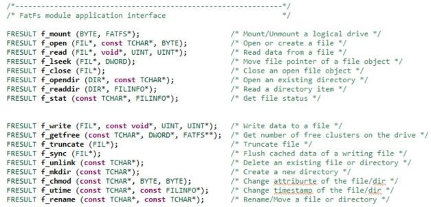
FatFs APIs
Basically, FatFs library hides the complexity of dealing with the driver functions directly, however, it is worth noting that internally, the FatFs calls the SD host controller driver’s functions to implement its functionality(aka disk IOs). FatFs library could be used in both standalone systems or as part of an operating system. The way we are using it in this lab is in standalone system, where no OS support was included. The figure below illustrates the layers of lab7 software stack running on the Zynq ARM processor:

Lab7 Software Stack
The above figure also shows how the application, library, driver, and hardware interact with each other. It is clear that the complexity of dealing with the hardware and driver directly has been abstracted and simplified through the use of the FatFs library. It is also evident that the application is effectively interacting with the hardware (SD card) using the user friendly APIs of the FatFs. The FatFs library is translating these APIs to function calls to the XSdPs driver, while the later will write to the memory-mapped region of the SD host controller to interact with the hardware, this is typically achieved through Xil_out32(), Xil_in32() functions.
The FatFs supported by Xilinx SDK is compatible with all three FAT subtypes: FAT12, FAT16, and FAT32. These three subtypes have different features in terms of disk utilization, maximum partition size, and file names length. FAT32 is an extension of the FAT16, the original FAT12 (aka FAT) was first introduced way back in 1981 in the DOS system. The subtype used for this lab is the upgraded FAT (FAT32).
E-FatFs APIs
To use the FatFs library, first you need to declare an instance of type file system (FATFS) to be associated with the SD card (s) present in the system.
![]()
Similarly, you need to create an instance of type file (FIL) for file(s) to be used in application.
![]()
In addition to that, declare a variable to hold the return value of the FatFs APIs. This variable should be of type (FRESULT). Examining the value returned in this variable can tell us whether an API succeeded or failed, and if failed we would know exactly what went wrong.

The FRESULT falls between 19 values, any value other than zero means a failure in execution. The interpretation of these values is as follows:

FatFs Return Values(FRESULT)
After defining these three variables, we can start using the APIs. The first API that should be present in all applications using FatFs library is the f_mount().

FatFs f_mount() format
f_mount() initializes an SD card and associates an instance of type FATFS with it. f_mount() takes three parameters: pointer to the FATFS instance, logical drive number (if there is only one SD card in the system its 0:/ ), and an option to have a delayed mount.
Note: this function can be also used to unmount an SD card by passing NULL in the first parameter.
The function returns FRESULT value similar to all FatFs APIs .

f_mount() with checked returned status
Path in the above example is a string pointer to the logical drive number:
![]()
It is a highly recommended practice to always check the value returned by any API, and if an error occurs it is typically safer to do the following:
1.Return to caller.
2.Notify user about the nature of the error.
After a successful call to f_mount(), a card is initialized and ready to be used. Similar to the way we handle files on our laptops and desktops, we will do similar steps here, in other words, in order to read/write a file, first we open it, then read/modify as needed, finally save and close it.
The f_open() function is used to create or to open a file. The function takes three parameters: a pointer to the file instance, name of the file including its path, and access mode.

FatFs f_open() format
For the sake of simplicity, files are saved directly on the root of the SD card, however, directories are supported and can be created to organize files. The access mode determines whether we are creating a new file, or opening an existing file, and it also controls other parameters such as overwriting:

FatFs Access Mode
Example 1: Create a new file named “Record.txt” on the root directory of an SD card, if the file already exists it will be truncated and overwritten.
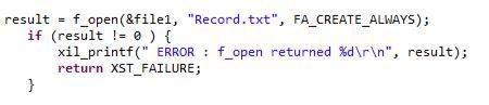
Example 1 solution
Example 2: Open a file named “temperature.txt” available on the root directory of an SD card, the file is to be read from and written to.

Example 2 solution
Now we know how to open a file in FatFS, the next thing to master is how to read from it and write to it.
In order to read from a file, it should have already been opened using f_open()function in FA_READ mode. A buffer is declared to hold the data read from the file. The type of the buffer is dependent on the data stored in the file. As for the size of the buffer, it is application dependent,however, always take into consideration memory word alignment.
Example 3: Assume a file contains long strings of characters, and we want to read 9 characters at a time. The buffer to be declared in such scenario is :
![]()
Example 3 solution
Note: you always need to declare a buffer with size+1, as the last location in the buffer is reserved for the NULL terminator.
It is also important to define an unsigned integer to keep track of how many bytes have been read from the file (counter). This is useful in many situations, like determining if end of the file(EOF) is reached.
![]()
Now, let’s talk about the function that actually do the reading f_read(), it takes four parameters: a pointer to the file instance previously opened using f_open() in FA_READ mode, a buffer to store the read data, the number of bytes to be read, and a pointer to the counter variable.

FatFs f_read() format
In the following example 4 bytes are read and saved in buffer “buff”. On a successful read operation, count should hold the value 4 .

f_read() reading 4 bytes from a file
If the opposite is needed, if data is to be written to a file, then f_write() function is called.

FatFs f_write() format
f_write() takes similar parameters to f_read(), but this time the buffer would contain the data to be written.
Example 4: save 9 bytes of data held in “buff” in a file associated with file instance file3. On a successful write operation, count would hold the value 9.

Example 4 solution
By using standard C functions, such as the sprintf(), you can format data in a write buffer the way you want.
It is recommended to close any file that is no longer needed to reserve resources. This is achieved by calling function f_close().
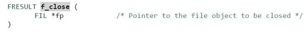
FatFs f_close() format
Example 5: closing file1 (no longer needed)
![]()
Example 5 solution
Objectives
1.Introduce non-volatile memories available on the Zedboard.
2.Examine the general structure of an SD card, and how the SD card attached to the Zedboard is wired to the chip.
3.Understand the different hardware and software components needed to access SD cards efficiently.
4.Emphasize on the benefits of using libraries on top of drivers to hide complexities and enable broader usages of hardware.
5.Practice FatsFs Application Programming Interface (API).
6.Build a simple logging application.
Procedures
A-Copy lab5 content into a new directory
Follow the same four steps in Procedures-A of Lab6. However, in Step1 name the new folder “lab7″.
B-Enable SD0 Host Controller on PS
1.Double click on the zynq_interrupt_system_i block diagram file to open the block diagram.

Block Diagram File
2.In the diagram view, double click on Zynq Processing System to open the Re-customize IP window.
3.Click on MIO Configuration-> I/O Peripherals and enable SD0. Change bank 1 I/O Voltage to LVCMOS 1.8V. Then, do the required modifications so that it matches the figure below.

MIO Configration for SD0
Make sure to disable the Pullup resisters for MIO 40-45 , and change its speed to fast. The Card detect signal “CD” and the write protect signal “WP” need to be enabled if you wish not to use JP6 jumper on the board.
Note: The above modifications were made to meet the electrical interface specifications of the SD card connector (obtained from Zedboard user manual). The Interface is shown below, MIO signals are wired to the SD connector through the TI TXS02612 SDIO level translator.
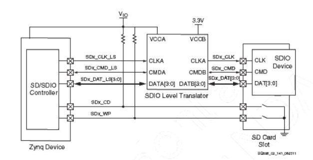
SD Card Interface
Click OK to close the the Re-customize IP window.
C-Regenerate Bitstream to reflect the new modification
In the Program and Debug section of the Flow Navigator pane, click Generate Bitstream. A dialog box will appear to ask you to save the modification you made, click Save .
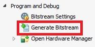
Generating Bitstream
Generating the Bitstream may take a while to complete, depending on the performance of your machine. After the Bitstream generation completes select View Reports in the dialog box, and click OK.
D-Export hardware design to SDK
1.Click File > Export > Export Hardware, make sure you select Include bitstream.

Export Hardware to SDK
2.Select File>Launch SDK. This will open up Launch SDK dialog, leave default options as as, and click OK. All the hardware files related to design have now been exported to SDK and we can work on the software.
We are now done with the hardware configuration of the system. You may close Vivado.
E-Working with SDK
1.In SDK, select File > New > Application Project.
2.In the Application Project window, enter the parameters as provided in the snapshot below:

New Standalone C Project – data_logger
In the next window, select Empty Application from the available templates and click Finish. This will compile the BSP and the related drivers.
3.Expand data_logger project directory, right click on src directory, New->Source File.

New C Source File – lab7.c
4.In the next window that shows up type “lab7.c” in the source file and click Finish. This will create an empty C file in the src directory.

lab7.c empty source file created in SDK
5.Right click on data_logger_bsp and select Board Support Package Settings.
6.In Board Support Package Settings, click on the box next to xilffs to include FatFs File System Library into the BSP and be able to use its API. Click OK .

Board Support Package Settings- Include FatFs File System Library
7.Paste the content of lab7.c ( Available on my Github page) in in the editor view of lab7.c of SDK , and click on Save  or hit (Ctrl+S) , by doing so both lab7 application, and its BSP are compiled automatically and the executable .elf file is generated( the default settings of SDK triggers compilation with Save). This is the executable file that the ARM processor on the PS side of the Zynq will execute.
lab7.c is an extended version of lab5.c. The additions on top of lab5.c are enclosed by comments as show in the figures below. The additions include modified main() and modified push buttons ISR BTN_Intr_Handler() .
main() now includes the code for mounting an initializing the SD card, and also creating file RECORDS.txt ( Lines 287-296).

modified main() – Lab7
The code to write to the file is inside modified push buttons ISR BTN_Intr_Handler() (Lines 130-169)

Writing to file inside pushbutton ISR everytime BTND is pressed
8.Select Xilinx Tools-> Program FPGA to download the Bitstream (this will take few seconds).

Downloading Bitstream to the PL
9.Select data_logger project directory-> Run As-> Launch on Hardware (GDB) to run data_logger application on the ARM processor. After the download is complete, every time you press the lower push button. A string is saved in file RECORDS.txt on the Zedboard SD card. you can view the content of this file by using a card reader. The content should be identical to the below :

RECORDS.txt created by the board and stored on its SD card
By this you have completed Lab7-Data Logging using SD Cards. You can find the complete solution of this lab in here.