LED跑马灯-库函数
一,GPIO知识回顾
1,四种输入模式:
    输入浮空
    输入上拉
    输入下拉
    模拟输入
2,四种输出模式:
    开漏输出
    开漏复用输出
    推挽输出
    推挽复用输出
3,三种最大输出速度
    2MHz
    10MHz
    50MHz
每组GPIO共16个IO口,含下7个寄存器
GPIOx_CRL  : 端口配置低寄存器
GPIOx_CRH  : 端口配置高寄存器
GPIOx_IDR  : 端口输入寄存器
GPIOx_ODR  : 端口输出寄存器
GPIOx_BSRR : 端口位设置/清除寄存器
GPIOx_BRR  : 端口位清除寄存器
GPIOx_LCKR : 端口配置锁存寄存器
二,LED硬件连接:
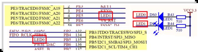
LED0连接PB5引脚
LED1连接PE5引脚
三,LED跑马灯实现流程
1,使能GPIO时钟
     使用IO口前先要使能相应的GPIO时钟

2,初始化IO口 GPIO_Init()
     配置IO口的引脚工作方式(最大速度,输入/输出模式)

3,操作IO口输出高低电平
     控制响应IO口输出高电平或低电平
四,源码分析
1,GPIO初始化函数
stm32f10x_gpio.h头文件中找到GPIO_Init函数声明
void GPIO_Init(GPIO_TypeDef* GPIOx, GPIO_InitTypeDef* GPIO_InitStruct);stm32f10x_gpio.c中找到GPIO_Init函数的实现
/**
  * @brief  Initializes the GPIOx peripheral according to the specified
  *         parameters in the GPIO_InitStruct.
  * @param  GPIOx: where x can be (A..G) to select the GPIO peripheral.
  * @param  GPIO_InitStruct: pointer to a GPIO_InitTypeDef structure that
  *         contains the configuration information for the specified GPIO peripheral.
  * @retval None
  */
void GPIO_Init(GPIO_TypeDef* GPIOx, GPIO_InitTypeDef* GPIO_InitStruct)
{
  uint32_t currentmode = 0x00, currentpin = 0x00, pinpos = 0x00, pos = 0x00;
  uint32_t tmpreg = 0x00, pinmask = 0x00;
  /* Check the parameters */
  assert_param(IS_GPIO_ALL_PERIPH(GPIOx));
  assert_param(IS_GPIO_MODE(GPIO_InitStruct->GPIO_Mode));
  assert_param(IS_GPIO_PIN(GPIO_InitStruct->GPIO_Pin));

/*---------------------------- GPIO Mode Configuration -----------------------*/
  currentmode = ((uint32_t)GPIO_InitStruct->GPIO_Mode) & ((uint32_t)0x0F);
  if ((((uint32_t)GPIO_InitStruct->GPIO_Mode) & ((uint32_t)0x10)) != 0x00)
  {
    /* Check the parameters */
    assert_param(IS_GPIO_SPEED(GPIO_InitStruct->GPIO_Speed));
    /* Output mode */
    currentmode |= (uint32_t)GPIO_InitStruct->GPIO_Speed;
  }
/*---------------------------- GPIO CRL Configuration ------------------------*/
  /* Configure the eight low port pins */
  if (((uint32_t)GPIO_InitStruct->GPIO_Pin & ((uint32_t)0x00FF)) != 0x00)
  {
    tmpreg = GPIOx->CRL;
    for (pinpos = 0x00; pinpos < 0x08; pinpos++)
    {
      pos = ((uint32_t)0x01) << pinpos;
      /* Get the port pins position */
      currentpin = (GPIO_InitStruct->GPIO_Pin) & pos;
      if (currentpin == pos)
      {
        pos = pinpos << 2;
        /* Clear the corresponding low control register bits */
        pinmask = ((uint32_t)0x0F) << pos;
        tmpreg &= ~pinmask;
        /* Write the mode configuration in the corresponding bits */
        tmpreg |= (currentmode << pos);
        /* Reset the corresponding ODR bit */
        if (GPIO_InitStruct->GPIO_Mode == GPIO_Mode_IPD)
        {
          GPIOx->BRR = (((uint32_t)0x01) << pinpos);
        }
        else
        {
          /* Set the corresponding ODR bit */
          if (GPIO_InitStruct->GPIO_Mode == GPIO_Mode_IPU)
          {
            GPIOx->BSRR = (((uint32_t)0x01) << pinpos);
          }
        }
      }
    }
    GPIOx->CRL = tmpreg;
  }
/*---------------------------- GPIO CRH Configuration ------------------------*/
  /* Configure the eight high port pins */
  if (GPIO_InitStruct->GPIO_Pin > 0x00FF)
  {
    tmpreg = GPIOx->CRH;
    for (pinpos = 0x00; pinpos < 0x08; pinpos++)
    {
      pos = (((uint32_t)0x01) << (pinpos + 0x08));
      /* Get the port pins position */
      currentpin = ((GPIO_InitStruct->GPIO_Pin) & pos);
      if (currentpin == pos)
      {
        pos = pinpos << 2;
        /* Clear the corresponding high control register bits */
        pinmask = ((uint32_t)0x0F) << pos;
        tmpreg &= ~pinmask;
        /* Write the mode configuration in the corresponding bits */
        tmpreg |= (currentmode << pos);
        /* Reset the corresponding ODR bit */
        if (GPIO_InitStruct->GPIO_Mode == GPIO_Mode_IPD)
        {
          GPIOx->BRR = (((uint32_t)0x01) << (pinpos + 0x08));
        }
        /* Set the corresponding ODR bit */
        if (GPIO_InitStruct->GPIO_Mode == GPIO_Mode_IPU)
        {
          GPIOx->BSRR = (((uint32_t)0x01) << (pinpos + 0x08));
        }
      }
    }
    GPIOx->CRH = tmpreg;
  }
}
GPIO_Init函数两个入参为GPIO_TypeDef和GPIO_InitTypeDef两个结构体指针
GPIO_TypeDef参数:
stm32f10x.h中找到GPIO_TypeDef结构体声明
/**
  * @brief General Purpose I/O
  * 定义了GPIO的7个寄存器
  */
typedef struct
{
  __IO uint32_t CRL;    // 端口配置低寄存器
  __IO uint32_t CRH;    // 端口配置高寄存器
  __IO uint32_t IDR;    // 端口输入寄存器
  __IO uint32_t ODR;    // 端口输出寄存器
  __IO uint32_t BSRR;   // 端口位设置/清除寄存器
  __IO uint32_t BRR;    // 端口位清除寄存器
  __IO uint32_t LCKR;   // 端口配置锁存寄存器
} GPIO_TypeDef;
GPIO_TypeDef有效性判断:
/** @defgroup GPIO_Exported_Types
  * GPIOA->GPIOG
  */

#define IS_GPIO_ALL_PERIPH(PERIPH) (((PERIPH) == GPIOA) || \
                                    ((PERIPH) == GPIOB) || \
                                    ((PERIPH) == GPIOC) || \
                                    ((PERIPH) == GPIOD) || \
                                    ((PERIPH) == GPIOE) || \
                                    ((PERIPH) == GPIOF) || \
                                    ((PERIPH) == GPIOG))
GPIO_InitTypeDef参数:
stm32f10x_gpio.h中找到GPIO_InitTypeDef结构体声明
/**
  * @brief  GPIO Init structure definition
  * GPIO_InitTypeDef结构体-设置IO口,速度,工作模式
  */
typedef struct
{
  uint16_t GPIO_Pin;             /*!< Specifies the GPIO pins to be configured.
This parameter can be any value of @ref GPIO_pins_define */

  GPIOSpeed_TypeDef GPIO_Speed;  /*!< Specifies the speed for the selected pins.
This parameter can be a value of @ref GPIOSpeed_TypeDef */

  GPIOMode_TypeDef GPIO_Mode;    /*!< Specifies the operating mode for the selected pins.
This parameter can be a value of @ref GPIOMode_TypeDef */

}GPIO_InitTypeDef;
GPIO_InitStruct->GPIO_Speed有效性校验
/**
  * @brief  Output Maximum frequency selection
  */

typedef enum
{
  GPIO_Speed_10MHz = 1,
  GPIO_Speed_2MHz,
  GPIO_Speed_50MHz
}GPIOSpeed_TypeDef;
#define IS_GPIO_SPEED(SPEED) (((SPEED) == GPIO_Speed_10MHz) || ((SPEED) == GPIO_Speed_2MHz) || \
                              ((SPEED) == GPIO_Speed_50MHz))
GPIO_InitStruct->GPIO_Mode有效性校验
/**
  * @brief  Configuration Mode enumeration
  * 八种输入/输出模式
  */

typedef enum
{ GPIO_Mode_AIN = 0x0,          // 模拟输入
  GPIO_Mode_IN_FLOATING = 0x04, // 浮空输入
  GPIO_Mode_IPD = 0x28,         // 下拉输入
  GPIO_Mode_IPU = 0x48,         // 上拉输入
  GPIO_Mode_Out_OD = 0x14,      // 开漏输出
  GPIO_Mode_Out_PP = 0x10,      // 推挽输出
  GPIO_Mode_AF_OD = 0x1C,       // 复用开漏输出
  GPIO_Mode_AF_PP = 0x18        // 复用推挽输出
}GPIOMode_TypeDef;

#define IS_GPIO_MODE(MODE) (((MODE) == GPIO_Mode_AIN) || \
                            ((MODE) == GPIO_Mode_IN_FLOATING) || \
                            ((MODE) == GPIO_Mode_IPD) || \
                            ((MODE) == GPIO_Mode_IPU) || \
                            ((MODE) == GPIO_Mode_Out_PP) || \
                            ((MODE) == GPIO_Mode_AF_OD) || \
                            ((MODE) == GPIO_Mode_AF_PP))
GPIO_InitStruct->GPIO_Pin有效性校验
/** @defgroup GPIO_pins_define
  * GPIO_Pin_0->GPIO_Pin_15
  */
#define GPIO_Pin_0                 ((uint16_t)0x0001)  /*!< Pin 0 selected */
#define GPIO_Pin_1                 ((uint16_t)0x0002)  /*!< Pin 1 selected */
#define GPIO_Pin_2                 ((uint16_t)0x0004)  /*!< Pin 2 selected */
#define GPIO_Pin_3                 ((uint16_t)0x0008)  /*!< Pin 3 selected */
#define GPIO_Pin_4                 ((uint16_t)0x0010)  /*!< Pin 4 selected */
#define GPIO_Pin_5                 ((uint16_t)0x0020)  /*!< Pin 5 selected */
#define GPIO_Pin_6                 ((uint16_t)0x0040)  /*!< Pin 6 selected */
#define GPIO_Pin_7                 ((uint16_t)0x0080)  /*!< Pin 7 selected */
#define GPIO_Pin_8                 ((uint16_t)0x0100)  /*!< Pin 8 selected */
#define GPIO_Pin_9                 ((uint16_t)0x0200)  /*!< Pin 9 selected */
#define GPIO_Pin_10                ((uint16_t)0x0400)  /*!< Pin 10 selected */
#define GPIO_Pin_11                ((uint16_t)0x0800)  /*!< Pin 11 selected */
#define GPIO_Pin_12                ((uint16_t)0x1000)  /*!< Pin 12 selected */
#define GPIO_Pin_13                ((uint16_t)0x2000)  /*!< Pin 13 selected */
#define GPIO_Pin_14                ((uint16_t)0x4000)  /*!< Pin 14 selected */
#define GPIO_Pin_15                ((uint16_t)0x8000)  /*!< Pin 15 selected */
#define GPIO_Pin_All               ((uint16_t)0xFFFF)  /*!< All pins selected */

#define IS_GPIO_PIN(PIN)           ((((PIN) & (uint16_t)0x00) == 0x00)
                                                    && ((PIN) != (uint16_t)0x00))
以初始化PE5为例:
 GPIO_InitTypeDef  GPIO_InitStructure;

 GPIO_InitStructure.GPIO_Pin = GPIO_Pin_5;         // LED0-->PB.5 端口配置
 GPIO_InitStructure.GPIO_Mode = GPIO_Mode_Out_PP;  // 推挽输出
 GPIO_InitStructure.GPIO_Speed = GPIO_Speed_50MHz; // IO口速度为50MHz

 GPIO_Init(GPIOB, &GPIO_InitStructure);            // 根据设定参数初始化GPIOB.5
2,设置输出电平函数
stm32f10x_gpio.h头文件中找到GPIO_SetBits,GPIO_ResetBits函数声明
void GPIO_SetBits(GPIO_TypeDef* GPIOx, uint16_t GPIO_Pin);
void GPIO_ResetBits(GPIO_TypeDef* GPIOx, uint16_t GPIO_Pin);
stm32f10x_gpio.c中找到GPIO_SetBits,GPIO_ResetBits函数的实现
/**
  * @brief  Sets the selected data port bits.
  * @param  GPIOx: where x can be (A..G) to select the GPIO peripheral.
  * @param  GPIO_Pin: specifies the port bits to be written.
  *   This parameter can be any combination of GPIO_Pin_x where x can be (0..15).
  * @retval None
  * 作用:设置某个IO口输出为高电平(1)。实际操作BSRR寄存器
  */
void GPIO_SetBits(GPIO_TypeDef* GPIOx, uint16_t GPIO_Pin)
{
  /* Check the parameters */
  assert_param(IS_GPIO_ALL_PERIPH(GPIOx));
  assert_param(IS_GPIO_PIN(GPIO_Pin));

  GPIOx->BSRR = GPIO_Pin;        // 操作的是BSRR寄存器低16位
}

/**
  * @brief  Clears the selected data port bits.
  * @param  GPIOx: where x can be (A..G) to select the GPIO peripheral.
  * @param  GPIO_Pin: specifies the port bits to be written.
  *   This parameter can be any combination of GPIO_Pin_x where x can be (0..15).
  * @retval None
  * 作用:设置某个IO口输出为低电平(0)。实际操作的BRR寄存器。
  */
void GPIO_ResetBits(GPIO_TypeDef* GPIOx, uint16_t GPIO_Pin)
{
  /* Check the parameters */
  assert_param(IS_GPIO_ALL_PERIPH(GPIOx));
  assert_param(IS_GPIO_PIN(GPIO_Pin));

  GPIOx->BRR = GPIO_Pin;        // 操作的是BRR寄存器低16位
}
设置IO口输出电平,还有不常用到的两个函数:
void GPIO_WriteBit(GPIO_TypeDef* GPIOx, uint16_t GPIO_Pin, BitAction BitVal);
void GPIO_Write(GPIO_TypeDef* GPIOx, uint16_t PortVal);
3,读取输出电平函数
uint8_t GPIO_ReadOutputDataBit (GPIO_TypeDef* GPIOx, uint16_t GPIO_Pin);
//作用:读取某个GPIO的输出电平。实际操作的是GPIO_ODR寄存器。
//例如:
    GPIO_ReadOutputDataBit(GPIOA, GPIO_Pin_5);//读取GPIOA.5的输出电平

uint16_t GPIO_ReadOutputData(GPIO_TypeDef* GPIOx);
//作用:读取某组GPIO的输出电平。实际操作的是GPIO_ODR寄存器。
//例如:
 GPIO_ReadOutputData(GPIOA);//读取GPIOA组中所有io口输出电平
4,读取输入电平函数
uint8_t GPIO_ReadInputDataBit(GPIO_TypeDef* GPIOx, uint16_t GPIO_Pin);
//作用:读取某个GPIO的输入电平。实际操作的是GPIOx_IDR寄存器。
//例如:
  GPIO_ReadInputDataBit(GPIOA, GPIO_Pin_5);//读取GPIOA.5的输入电平

uint16_t GPIO_ReadInputData(GPIO_TypeDef* GPIOx);
//作用:读取某组GPIO的输入电平。实际操作的是GPIOx_IDR寄存器。
//例如:
 GPIO_ReadInputData(GPIOA);//读取GPIOA组中所有io口输入电平
五,LED跑马灯-库函数实现代码
新建LED头文件:HAERWARE->LED->led.h 定义LED初始化函数
#ifndef __LED_H
#define __LED_H

void LED_Init(void);

#endif
新建:HAERWARE->LED->led.c 实现LED初始化函数
#include "led.h"
#include "stm32f10x.h"

void LED_Init(void)
{

    GPIO_InitTypeDef GPIO_InitStructure;

    //使能GPIOB时钟
    RCC_APB2PeriphClockCmd(RCC_APB2Periph_GPIOB,ENABLE);
    //使能GPIOE时钟
    RCC_APB2PeriphClockCmd(RCC_APB2Periph_GPIOE,ENABLE);

    //配置PB5
    GPIO_InitStructure.GPIO_Mode=GPIO_Mode_Out_PP;
    GPIO_InitStructure.GPIO_Pin=GPIO_Pin_5;
    GPIO_InitStructure.GPIO_Speed=GPIO_Speed_50MHz;
    GPIO_Init(GPIOB,&GPIO_InitStructure);
    GPIO_SetBits(GPIOB,GPIO_Pin_5);

    //配置PE5
    GPIO_InitStructure.GPIO_Mode=GPIO_Mode_Out_PP;
    GPIO_InitStructure.GPIO_Pin=GPIO_Pin_5;
    GPIO_InitStructure.GPIO_Speed=GPIO_Speed_50MHz;
    GPIO_Init(GPIOE,&GPIO_InitStructure);
    GPIO_SetBits(GPIOE,GPIO_Pin_5);

}
USER->main.c 主函数编写LED跑马灯代码
#include "stm32f10x.h"
#include "led.h"
#include "delay.h"

int main(void)
{

    delay_init();    // 初始化延时函数
    LED_Init();        // 初始化LED

    while(1){

        GPIO_SetBits(GPIOB, GPIO_Pin_5);
        GPIO_SetBits(GPIOE, GPIO_Pin_5);
        delay_ms(500);

        GPIO_ResetBits(GPIOB, GPIO_Pin_5);
        GPIO_ResetBits(GPIOE, GPIO_Pin_5);
        delay_ms(500);

    }

}