Wheeled mobile robots may be classified in two major categories, omnidirectional and nonholonomic. Omnidirectional mobile robots have no equality constraints on the chassis velocity $\dot{q}=(\dot{\phi},\dot{x},\dot{y})$ Omnidirectional wheeled mobile robots typically employ either omniwheel or mecanum wheels. Omniwheels and mecanum wheels are not steered, only driven forward or backward. Because of their small diameter rollers, omniwheels and mecanum wheels work best on hard, flat ground. 全方位运动平台通常装有全向轮:omniwheels(全向轮)或 mecanum wheels(麦克纳姆轮)。借助于横向移动和原地回旋的特性,全方位运动平台可方便的穿梭于狭窄拥挤空间中,灵活完成各种任务,相比传统移动平台有明显优势。
全方位运动系统中,Mecanum轮应用最广泛。Mecanum轮(又称瑞典轮)是瑞典Mecanum AB公司工程师Bengt Ilron提出的特殊轮系,其特点为沿轮毅圆周排布着与轮子成一定角度且可绕自身轴线进行旋转的辊子。由三个或以上Mecanum 轮按照一定方式排列组成的移动平台具有平面内三个自由度,可同时独立的前后、左右和原地旋转运动,可在不改变自身姿态的情况下向任意方向移动。
其运动学本质是:轮毂外围安装一周与轮毂轴线呈一定角度的无动力辊子作为轮胎,该辊子不仅可绕轮毂轴公转,也能在地面摩擦力作用下绕各自的支撑芯轴自转,两种运动的合成使得接触地面的辊子中心合速度与轮毂轴有一定的夹角,通过调节轮毂速度可改变辊子中心合速度的大小和方向。由同样结构的若干Mecanum 轮按一定规则组成的轮组系统,通过改变各轮毂速度的线性组合,进而控制运动系统中心合速度大小和方向,使机器人实现平面3自由度全方位运动。由于其外观上与斜齿轮相似,麦克纳姆轮也有齿轮啮合时相类似的问题:为了保证运动的平稳性,当前一个辊子与地面即将分离时,后一个辊子必须与地面接触。
全向轮运动学
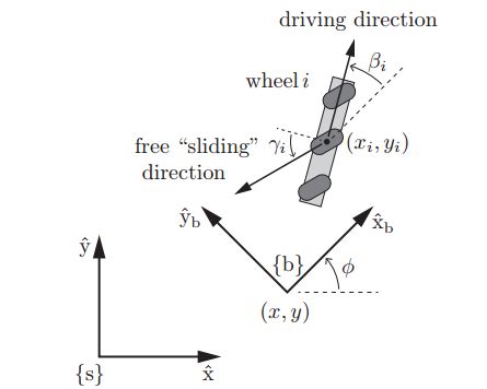
如下图所示,坐标系{S}为空间中静止的参考系,坐标系{b}固定在车身上随机器人运动。那么机器人在静止参考系中的位置和姿态可以用向量$q$描述,$q=(\phi,x,y)$。在自身参考系{b}中的线速度及角速度为$\upsilon _b=(\omega_{bz},v_{bx},v_{by})$
那么两个参考系之间速度的转换公式如下:
全方位移动机器人必须安装至少3个全向轮,才能实现以任意三维速度$\dot{q}=(\dot{\phi},\dot{x},\dot{y})$进行运动。下图为两种典型的全向移动机器人,一种装有3个全向轮,另一种装有4个麦克纳姆轮。
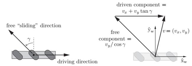
为了控制全向移动机器人,我们需要知道给每个轮子多大的角速度才能使机器人达到目标速度$\dot{q}$。为了解答这个问题,我们需要理解单个轮子的运动学,为此建立如下图所示的轮子坐标系:
坐标系$\hat{X_w}-\hat{Y_w}$建立在轮子中心,根据速度合成定理车轮中心的速度$v=(v_x,v_y)$满足下面的公式:
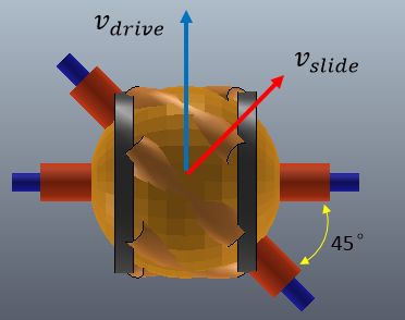
其中$\gamma$为小辊子滚动方向与驱动轮平面的夹角(通常全向轮为0°,麦克纳姆轮为±45°),$v_{drive}$是驱动速度,$v_{slide}$是自由滑动的速度。解方程(13.3)可以得到
假设轮子半径为$r$,轮子转动的角速度为$u$,那么根据上式可得:
为了推导出从小车速度$\dot{q}=(\dot{\phi},\dot{x},\dot{y})$到轮子$i$的角速度$u_i$的转换关系,参考最上面的坐标系布置图。轮子坐标系在小车坐标系{b}中的位置和姿态可以用向量$(\beta_i,x_i,y_i)$来表达,其中轮子半径为$r_i$,辊子滑动角度为$\gamma_i$。那么从$\dot{q}$到$u_i$的转换关系如下:
从右到左进行解读:第一个变换矩阵将静止坐标系下的$\dot{q}$变换为小车局部坐标系{b}中的$\upsilon _b$;第二个变换矩阵将小车的局部速度转换为坐标系{b}中的轮子线速度;第三个变换矩阵将坐标系{b}中的轮子线速度转换为轮子坐标系$\hat{X_w}-\hat{Y_w}$中的线速度;最后一个变换矩阵将依据公式(13.4)计算轮子角速度。
将这几个矩阵合并,可以得到对单个轮子的变换矩阵$h_i(\phi)$如下:
对于一个全向移动机器人来说,轮子数量$m \geqslant 3 $,矩阵$H(\phi) \in R^{m \times 3}$将静止参考系中的机器人速度$\dot{q} \in R^3$转换为轮子驱动角速度$u \in R^m$,将m行$h_i(\phi)$向量堆叠到一起组成矩阵$H(\phi)$,有如下公式:
根据上式我们也可以直接计算出小车局部坐标系下的速度和驱动轮角速度之间的关系,这时转换矩阵将不依赖小车在静止参考坐标系中的朝向角$\phi$:
小车上轮子的位置和朝向$(\beta_i,x_i,y_i)$,以及辊子夹角$\gamma_i$的选择必须使得矩阵$H(0)$的秩为3。如果rank(H) < 3,则系统中存在奇异位形,反映在运动学上就是失去部分自由度,即小车不能实现全方位运动。
由于全向轮结构和运动学的特殊性,系统中并不是任一种轮组排列结构形式都可实现全方位运动,多轮构成的系统运动能力和运动控制性能及其驱动性能均与轮组的结构形式密切相关。下面就是两种典型的布局,麦克纳姆轮在小车中的朝向都一致$\beta_i=0$:
根据上面的公式,3个全向轮布置的移动机器人运动学模型为:
4个麦克纳姆轮布置的移动机器人运动学模型为:
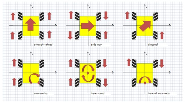
对麦克纳姆轮型移动机器人来说,为向前移动,所有轮子要以相同的速度向前转动;为了侧向移动,1、3轮向前转,2、4轮向后转,转速要相同...
V-rep中全向移动机器人仿真
在V-rep的模型浏览器中可以找到麦克纳姆轮组件:
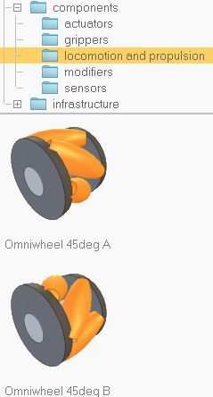 为了搭建麦克纳姆轮的模型,一种很自然的想法是在轮毂上创建多个关节,并在关节上添加与地面接触的辊子。这样虽然符合实际情况,但是会影响仿真速度、仿真稳定性及精度。There is the obvious natural approach to simulate them by modelling each auxiliary wheel on top of the actuated wheel. This will slow down simulation, make it less stable, and also less precise. But this is possible. The better approach for this is to use a trick: instead of using a complicated wheel, simply use a sphere, attached to a passive axis, itself attached to a non-respondable sphere, itself attached to an actuated axis. Then, in each simulation step, reset the orientation of the passive wheel.
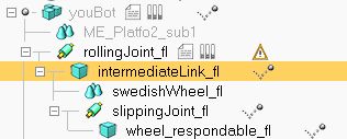
我们看看V-rep中麦克纳姆轮是怎样搭建起来的(参考V-rep Forum里的这两个问题:Object Orientation around an Axis,Robotino problem)。在图层中将轮子的虚拟外形隐藏,显示两个转动关节以及实际与地面接触的“轮子”。从下图可以看出这个实际的轮子是由一个球体模拟的,这个球不仅可以绕着驱动轴转动,还可以绕着另一个虚拟轴free "sliding" joint转动,转动方向即为free "sliding" direction。
这两个轴之间的角度即为上面讨论的$\gamma$角。注意要从底面方向上看(可以切换到bottom view),因为轮子与地面接触的辊子在最下端,不要看反了:
V-rep中提供的mecanum轮由两个转动关节和两个球体组成,用来模拟实际复杂的轮子。The wheel is composed by 2 spheres and 2 revolute joints in following configuration: robotBody → activeJoint → nonRespondableSphere → passiveJoint → respondableSphere
V-rep中进行动力学仿真时对dynamic chain以及物体质量属性等参数有一系列要求,为了能正确进行仿真必须遵守这些准则,具体要参考官方文档:Designing dynamic simulations.
Dynamically enabled joints are joints that are in force or torque mode, and that have a shape as parent object and exactly one child object which must be a non-static shape. Following are a few example situations where a joint won't be dynamically enabled:
- the joint is not in force or torque mode, and the joint is not operating in a hybrid fashion.
- the joint's parent is not a shape.
- the joint has more than one child object.
- the joint directly connects to another joint.
- the joint (or one of the two shapes it connects) is located in a model (hierarchy tree) that is not dynamically simulated
注意V-rep中的球型关节本质上是直接由三个正交的转动副串接而成的。考虑到上面第4点,这三个关节直接相互串接,因此球型关节不能设置为Torque/force模式,它总是工作在passive模式。Spherical joints are always passive joints, and cannot act as motors.
[Two equivalent mechanisms (in this configuration): spherical joint (left) and 3 revolute joints (right)]
Never have a static shape between two dynamic items. The static shape will interrupt the logical behaviour of the dynamic chain:
[Wrong and correct construction]
基于这几点考虑要在activeJoint → passiveJoint的运动链中插入nonRespondableSphere,这个中间连接件是non-static & non-respondable的。如果是static类型,那么仿真时在驱动关节旁边会出现警告图标。Objects that are supposed to by dynamically simulated but which, for a reason or another cannot be dynamically simulated, will display following the warning icon:
在进行动力学仿真时点击工具栏上的Visualize and verify dynamic content按钮,就可以以不同颜色显示各个图层(包括隐藏图层)中的动态物体。
[Dynamic content visualization button]
下面是几种颜色类型。pure shape物体的边线为黑色,其中non-static&respondable类型的物体面为红色,static&respondable类型的物体面为白色。Torque/force模式下的关节如果motor enabled颜色为红色,如果没有enabled,颜色为蓝色。注意点击显示动态内容的按钮后,Passive等模式下的关节将不会在仿真时显示出来。
从下图我们可以很清楚地看出YouBot由不同动力学特性的部件构成。其中,以蓝色显示的自由关节在底盘运动过程中始终保持水平,没有随着父节点的驱动关节一起旋转。这是因为在脚本执行过程中会周期性的调用函数设置该关节相对于驱动关节的位置和姿态。如果我们将这两行代码注释掉,或者直接disable这个脚本,那么在仿真过程中这个自由关节会随着驱动关节一起旋转,底盘运动时会产生奇怪的行为。
下面是单个麦克纳姆轮的代码。There must be a non-threaded child script attached to one of those objects, preferably the first joint. It is in charge of resetting the respondable sphere and reorienting the passive joints in each simulation loop.
-- Following script resets the second joint on the omni-wheel (important to achieve the desired omni-wheel effect)

if (sim_call_type==sim_childscriptcall_initialization) then
    rolling = simGetObjectHandle('rollingJoint_fl')
    slipping = simGetObjectHandle('slippingJoint_fl')
    wheel = simGetObjectHandle('wheel_respondable_fl')
end


if (sim_call_type==sim_childscriptcall_actuation) then
    simResetDynamicObject(wheel)
    simSetObjectPosition(slipping,rolling,{0,0,0})
    simSetObjectOrientation(slipping,rolling,{-math.pi/4,0,0})
    simSetObjectPosition(wheel,rolling,{0,0,0})
    simSetObjectOrientation(wheel,rolling,{0,0,0})
end
接下来看一个用麦克纳姆轮搭建的移动机器人的例子。在模型浏览器中的移动机器人目录下找到KUKA YouBot模型,并将其拖入新建的场景中:
删掉机械臂相关的结构和代码,选中youBot进行仿真会弹出一个GUI界面,通过上面的滑块可以控制底盘的前进后退、横向移动以及转动速度:
注意YouBot的原始Lua代码中控制麦克纳姆轮底盘运动时并没有按照实际的公式去计算4个轮子的角速度(忽略了轮子尺寸,以及轮子间距等几何参数),在V-rep中测得这些参数后再修改公式的代码如下:
if (sim_call_type==sim_childscriptcall_initialization) then

    -- Make sure we have version 2.4.12 or above (the omni-wheels are not supported otherwise)
    v=simGetInt32Parameter(sim_intparam_program_version)
    if (v<20412) then
        simDisplayDialog('Warning','The YouBot model is only fully supported from V-REP version 2.4.12 and above.&&nThis simulation will not run as expected!',sim_dlgstyle_ok,false,'',nil,{0.8,0,0,0,0,0})
    end

    --Prepare initial values and retrieve handles:
    wheelJoints={-1,-1,-1,-1} -- front left, rear left, rear right, front right
    wheelJoints[1]=simGetObjectHandle('rollingJoint_fl')
    wheelJoints[2]=simGetObjectHandle('rollingJoint_rl')
    wheelJoints[3]=simGetObjectHandle('rollingJoint_rr')
    wheelJoints[4]=simGetObjectHandle('rollingJoint_fr')

    youBot=simGetObjectHandle('youBot')
    ui=simGetUIHandle('youBot_UI')
    simSetUIButtonLabel(ui,0,simGetObjectName(youBot)..' user interface') -- Set the UI title (with the name of the current robot)

    forwBackVelRange={-240*math.pi/180,240*math.pi/180}  -- min and max wheel rotation vel. for backward/forward movement
    leftRightVelRange={-240*math.pi/180,240*math.pi/180} -- min and max wheel rotation vel. for left/right movement
    rotVelRange={-240*math.pi/180,240*math.pi/180}       -- min and max wheel rotation vel. for left/right rotation movement

    forwBackVel=0
    leftRightVel=0
    rotVel=0

    r= 0.05  -- wheel radius(m)
end


if (sim_call_type==sim_childscriptcall_actuation) then

    buttonID=simGetUIEventButton(ui)
    if (buttonID==200) then -- Forward/backward slider was changed
        forwBackVel=forwBackVelRange[1]+simGetUISlider(ui,buttonID)*0.001*(forwBackVelRange[2]-forwBackVelRange[1])
    end
    if (buttonID==201) then -- left/right slider was changed
        leftRightVel=leftRightVelRange[1]+simGetUISlider(ui,buttonID)*0.001*(leftRightVelRange[2]-leftRightVelRange[1])
    end
    if (buttonID==202) then -- left/right rotation slider was changed
        rotVel=rotVelRange[1]+simGetUISlider(ui,buttonID)*0.001*(rotVelRange[2]-rotVelRange[1])
    end
    if (buttonID==212) then -- stop button was clicked
        forwBackVel=0
        leftRightVel=0
        rotVel=0
        -- Reset the wheel movement sliders to the neutral position:
        simSetUISlider(ui,200,500)
        simSetUISlider(ui,201,500)
        simSetUISlider(ui,202,500)
    end

    -- Now apply the desired wheel velocities:
--[[
    simSetJointTargetVelocity(wheelJoints[1],-forwBackVel-leftRightVel-rotVel)
    simSetJointTargetVelocity(wheelJoints[2],-forwBackVel+leftRightVel-rotVel)
    simSetJointTargetVelocity(wheelJoints[3],-forwBackVel-leftRightVel+rotVel)
    simSetJointTargetVelocity(wheelJoints[4],-forwBackVel+leftRightVel+rotVel)
--]]
    simAddStatusbarMessage(string.format("Vx:%.2f  Vy:%.2f  Rot:%.2f", forwBackVel,leftRightVel,rotVel))

    simSetJointTargetVelocity(wheelJoints[1], (-forwBackVel-leftRightVel-0.38655*rotVel)/r )
    simSetJointTargetVelocity(wheelJoints[2], (-forwBackVel+leftRightVel-0.38655*rotVel)/r )
    simSetJointTargetVelocity(wheelJoints[3], (-forwBackVel-leftRightVel+0.38655*rotVel)/r )
    simSetJointTargetVelocity(wheelJoints[4], (-forwBackVel+leftRightVel+0.38655*rotVel)/r )
end
修改代码后V-rep的状态栏中会显示滑块设定的角速度。为了验证公式的正确性,我们可以添加一个Graph来记录底盘旋转时的角速度,与设定值进行对比。经过比较,发现设定值与实际值相差很小。由于尺寸测量时的误差以及物理仿真涉及到轮子与地面的接触、摩擦等因素影响,还是会存在一定的误差。
参考:
麦克纳姆轮浅谈
万向轮、全向轮的优缺点是什么?
麦克纳姆轮和全向轮他们的优缺点分别是什么?
Mecanum轮结构特征及运动误差
Mecanum四轮全方位移动机构运动分析与仿真
Mecanum轮全方位移动机器人技术及其应用
Mecanum四轮系统全方位运动性能分析及布局结构优选
Mecanum wheel-Wikipedia
Introduction to Autonomous Mobile Robots. Chapter 3 Mobile Robot Kinematics
Modern Robotics Mechanics, Planning, and Control. Chapter 13 Omnidirectional Wheeled Mobile Robots

