并行转串行 串行转并行输出模块
并行转串行 串行转并行输出模块
夏宇闻Verilog 第15章学习笔记
- 通信协议:scl为高,sda由高跳变低,start;scl为高,sda由低跳变为高,stop;scl为低,sda数据位才能变化
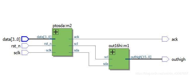
- 两个模块ptosda和out16hi,将ptosda并转串模块的串行输出给out16hi串转并模块,输出对应的高位电平
代码如下
//************************并行数据转一种特殊串行数据流********************************
//模块名称:M1 转换模块
//说明:data用scl和sda传输,sclk为输入时钟,data[3:0]数据流,ack为请求发送数据
//**********************************************************************************

module ptosda(rst_n,sclk,ack,scl,sda,data);

input rst_n,sclk;
input[3:0] data;
output scl,sda,ack;

reg scl,link_sda,ack,sda_buf;              //ack ask for new data
reg[3:0] data_buf;
reg[7:0] state;

assign sda=link_sda?sda_buf:1'b0;             //link_sda控制sda_buf输出到串行总线上

parameter Ready=8'b00000000,
          Start=8'b00000001,
		   bit1=8'b00000010,
		   bit2=8'b00000100,
           bit3=8'b00001000,
           bit4=8'b00010000,
           bit5=8'b00100000,
           Stop=8'b01000000,
           Idle=8'b10000000;

always@(posedge sclk or negedge rst_n)begin      //sclk产生scl为sclk的2T
 if(!rst_n)begin
  scl<=1;
 end
 else begin
  scl<=~scl;
 end
end

always@(posedge ack)begin	   //请求新数据时存入并行主线的数据
 data_buf<=data;
end
//******************主状态机:产生控制信号,根据data_buf中的数据,按照协议产生串行信号
always@(negedge sclk or negedge rst_n)begin
 if(!rst_n)begin
  link_sda<=0;          //sda_buf与sda串行总线断开
  state<=Ready;
  sda_buf<=1;
  ack<=0;
 end
 else begin
  case(state)
   Ready:begin
          if(ack)begin            //并行数据已经到达
  		   link_sda<=1;
           state<=Start;
		  end
		  else begin
		   link_sda<=0;
		   state<=Ready;
		   ack<=1;
		   //sda_buf<=1;
		  end
		 end
   Start:begin
          if(scl && ack)begin       //产生sda开始的信号  (开始是scl为高,sda由高变低)
           sda_buf<=0;
		   state<=bit1;
		  end
		  else state<=Start;
         end
	bit1:begin
	      if(!scl)begin
		   sda_buf<=data_buf[3];
		   state<=bit2;
		  end
		  else state<=bit1;
		 end
    bit2:begin
	      if(!scl)begin
		   sda_buf<=data_buf[2];
		   state<=bit3;
		  end
		  else state<=bit2;
		 end
	bit3:begin
	      if(!scl)begin
		   sda_buf<=data_buf[1];
		   state<=bit4;
		  end
		  else state<=bit3;
		 end
	bit4:begin
	      if(!scl)begin
		   sda_buf<=data_buf[0];
		   state<=bit5;
		  end
		  else state<=bit4;
		 end
	bit5:begin
	      if(!scl)begin
		   sda_buf<=0;             //为产生结束信号做准备,先把sda变低
		   state<=Stop;
		  end
		  else state<=bit5;
		 end
	Stop:begin
	      if(scl)begin
		   sda_buf<=1;
		   state<=Idle;
		  end
		  else state<=Stop;
		 end
	Idle:begin
	      link_sda<=0;
		  state<=Ready;
		 end
	default:begin
	         link_sda<=0;
			 sda_buf<=1;
			 state<=Ready;
			end
  endcase
 end
end

endmodule
//*******************************************//
//模块功能:接收串行数据,按照数据值在相应位输出高电平
//可综合
//***************************************************

module out16hi(scl,sda,outhigh);

input scl,sda;           //串行数据输入
output reg[3:0] outhigh;
reg[5:0] mstate /*synthesis preserve*/;

reg[3:0] pdata,pdatabuf;  //记录串行数据位时候,用寄存器和最终数据寄存器;
reg Startflag,Endflag;

always@(negedge sda)begin
 if(scl)begin
  Startflag<=1;
 end
 else if(Endflag)begin
  Startflag<=0;
 end
end

always@(posedge sda)begin
 if(scl)begin
  Endflag<=1;
  pdatabuf<=pdata;          //把收到的四位数据存入寄存器
 end
 else Endflag<=0;
end

parameter Ready=6'b000000,
          sbit0=6'b000001,
		  sbit1=6'b000010,
		  sbit2=6'b000100,
		  sbit3=6'b001000,
		  sbit4=6'b010000;

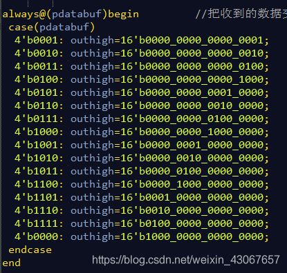
always@(pdatabuf)begin         //把收到的数据变为相应高电平
 case(pdatabuf)
  4'b0001: outhigh=16'b0000_0000_0000_0001;
  4'b0010: outhigh=16'b0000_0000_0000_0010;
  4'b0011: outhigh=16'b0000_0000_0000_0100;
  4'b0100: outhigh=16'b0000_0000_0000_1000;
  4'b0101: outhigh=16'b0000_0000_0001_0000;
  4'b0110: outhigh=16'b0000_0000_0010_0000;
  4'b0111: outhigh=16'b0000_0000_0100_0000;
  4'b1000: outhigh=16'b0000_0000_1000_0000;
  4'b1001: outhigh=16'b0000_0001_0000_0000;
  4'b1010: outhigh=16'b0000_0010_0000_0000;
  4'b1011: outhigh=16'b0000_0100_0000_0000;
  4'b1100: outhigh=16'b0000_1000_0000_0000;
  4'b1101: outhigh=16'b0001_0000_0000_0000;
  4'b1110: outhigh=16'b0010_0000_0000_0000;
  4'b1111: outhigh=16'b0100_0000_0000_0000;
  4'b0000: outhigh=16'b1000_0000_0000_0000;
 endcase
end

always@(posedge scl)begin            //检测到开始 之后每次scl正跳变接收数据
 if(Startflag)begin
    case(mstate)
	  sbit0:begin
	         mstate<=sbit1;
			 pdata[3]<=sda;
			 $display("i am in sdabit0");
			end
	  sbit1:begin
	         mstate<=sbit2;
			 pdata[2]<=sda;
			 $display("i am in sdabit1");
			end
	  sbit2:begin
	         mstate<=sbit3;
			 pdata[1]<=sda;
			 $display("i am in sdabit2");
			end
	  sbit3:begin
	         mstate<=sbit4;
			 pdata[0]<=sda;
			 $display("i am in sdabit3");
			end
	  sbit4:begin
	         mstate<=sbit0;
			 $display("i am in sdastop");
			end
      default: mstate<=sbit0; //6'bxx_xxxx;
    endcase
 end
 else mstate<=sbit0;
end

endmodule
这里的状态机的Ready其实没有用到,不需要这个状态
//**********************顶层************************
//模块名称:顶层   文件名:top_bingxingzhuanchuanxing.v
//对ptosda和out16hi联合测试,ptosda能否并转串,out16hi能否把串对应输出高

`timescale 1ns/1ns


module top_bingxingzhuanchuanxing(sclk,outhigh,rst_n,data,ack);

input rst_n,sclk;
input[3:0] data;
output outhigh,ack;

wire scl,sda;

out16hi m1(.scl(scl),.sda(sda),.outhigh(outhigh));
ptosda m2(.rst_n(rst_n),.sclk(sclk),.ack(ack),.scl(scl),.sda(sda),.data(data));

endmodule
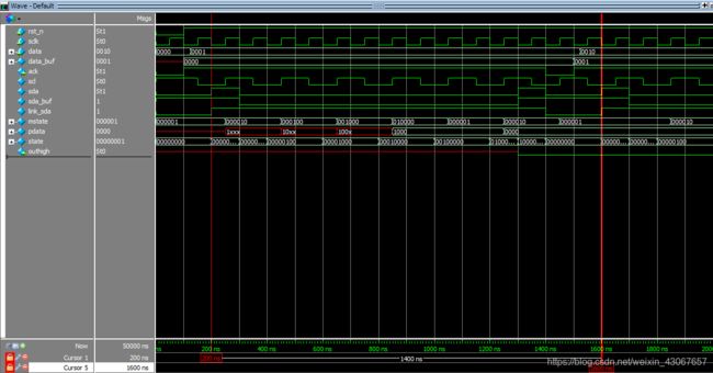
测试信号,data输入2’b0000,每收到一个ack,data+1
`timescale 1 ns/ 1 ns
`define halfperiod 50
module top_bingxingzhuanchuanxing_vlg_tst();

reg [3:0] data;
reg rst_n;
reg sclk;
// wires
wire ack;
wire outhigh;

// assign statements (if any)
top_bingxingzhuanchuanxing i1 (
// port map - connection between master ports and signals/registers
	.ack(ack),
	.data(data),
	.outhigh(outhigh),
	.rst_n(rst_n),
	.sclk(sclk)
);
initial
begin
rst_n=0;
#(`halfperiod*2) rst_n=1;
end

initial
begin
sclk=0;
data=0;
#(`halfperiod*1000)
$stop;
end

always #(`halfperiod) sclk=~sclk;

always@(posedge ack)
begin
#(`halfperiod/2) data=data+1;
end

endmodule
- 利用sclk产生scl,scl的周期为sclk的2倍
- 利用link_sda控制串行总线的开关
- 利用ack信号要求新的4位数据输入
- sclk下降沿控制主状态机state;
- scl上升沿在start_flag为1控制mstate


