HDLBits刷题合集—2 Basics
HDLBits刷题合集—2 Basics
HDLBits-2 Zero
Problem Statement
建立一个没有输入只有输出常数0的电路。
代码如下:
module top_module ( output zero );

	assign zero = 1'b0;

endmodule
HDLBits-3 Wire
Problem Statement
创建一个具有一个输入和一个输出的模块,其行为类似于线。

代码如下:
module top_module( input in, output out );

	assign out = in;

endmodule
HDLBits-4 Wire4
Problem Statement
创建一个有3个输入和4个输出的模块,它的行为就像这样连接的线:
a -> w
b -> x
b -> y
c -> z

代码如下:
module top_module(
    input a,b,c,
    output w,x,y,z );
	assign w = a;
    assign x = b;
    assign y = b;
    assign z = c;
endmodule
HDLBits-5 Notgate
Problem Statement
创建一个实现非门的模块。

代码如下:
module top_module( input in, output out );

	assign out = ~in;

endmodule
HDLBits-6 Andgate
Problem Statement
创建一个实现与门的模块。

代码如下:
module top_module(
    input a,
    input b,
    output out );

	assign out = a & b;

endmodule
HDLBits-7 Norgate
Problem Statement
创建一个实现或非门的模块。或非门是输出反相的或门。当用Verilog编写NOR(或非)函数时,它需要两个操作符。

代码如下:
module top_module(
    input a,
    input b,
    output out );

    assign out = ~ (a | b);

endmodule
HDLBits-8 Xnorgate
Problem Statement
创建一个实现XNOR(同或)门的模块。

代码如下:
module top_module(
    input a,
    input b,
    output out );

    assign out = a ^~ b;

endmodule
HDLBits-9 Wire declare
Problem Statement
到目前为止,电路已经足够简单,输出是输入的简单函数。随着电路变得越来越复杂,你将需要电线把内部元件连接在一起。当你需要使用连线时,你应该在第一次使用它之前,在模块的主体中声明它。(将来,您将遇到更多类型的信号和变量,它们也是以同样的方式声明的,但是现在,我们将从wire类型的信号开始)。

参考代码如下:
module top_module (
    input in,              // Declare an input wire named "in"
    output out             // Declare an output wire named "out"
);

    wire not_in;           // Declare a wire named "not_in"

    assign out = ~not_in;  // Assign a value to out (create a NOT gate).
    assign not_in = ~in;   // Assign a value to not_in (create another NOT gate).

endmodule   // End of module "top_module"
实现以下电路。创建两个中间线(命名任何你想命名的名称,关键字除外),将与门和非门连接在一起。注意,提供非门的连接实际上是连接出去的,所以不必在这里声明第三个wire。注意线是如何由一个源驱动的(一个门的输出),但可以提供多个输入。如果你遵循图中的电路结构,你应该以四个赋值语句结束,因为有四个信号需要赋值。

代码如下:
`default_nettype none
module top_module(
    input a,
    input b,
    input c,
    input d,
    output out,
    output out_n   );

    wire and1,and2;
    assign and1  = a & b;
    assign and2  = c & d;
    assign out   = and1 | and2;
    assign out_n = ~( and1 | and2);

endmodule
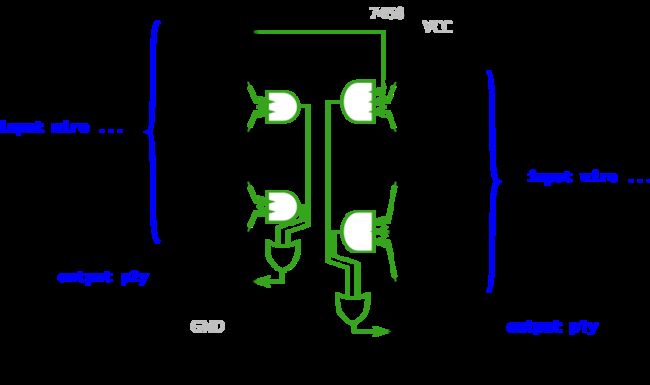
HDLBits-10 7458
Problem Statement
7458是一个有四个与门和两个或门的芯片。这个问题比7420稍微复杂一些。
创建与7458芯片具有相同功能的模块。它有10个输入和2个输出。您可以选择使用一条assign语句来驱动每条线,也可以选择声明4条线用作中间信号,其中每条内部线由其中一个与门的输出驱动。对于额外的练习,两种方法都可以尝试。
代码如下:
module top_module (
    input p1a, p1b, p1c, p1d, p1e, p1f,
    output p1y,
    input p2a, p2b, p2c, p2d,
    output p2y );
    /*
    wire and21,and22,and11,and12;
    assign and11 = p1a & p1b & p1c;
    assign and12 = p1d & p1e & p1f;
    assign and21 = p2a & p2b;
    assign and22 = p2c & p2d;
    assign p1y = and11 | and12;
    assign p2y = and21 | and22;
    */
    assign p1y = (p1a & p1b & p1c) | (p1d & p1e & p1f);
    assign p2y = (p2a & p2b) | (p2c & p2d);

endmodule
Note
新手一枚,主要分享博客,记录学习过程,后期参考大佬代码或思想会一一列出。欢迎大家批评指正!