eNSP搭建路由两侧客户PC端,打通链接,路由及客户PC里面的配置信息
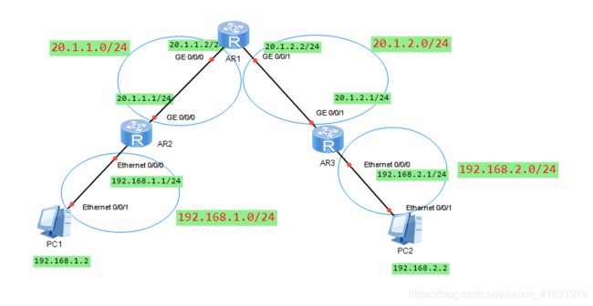
1.划分位置线路
2.规划路由表ip线路,创建网络拓扑
3.启动所有设备,发现颜色会有改变,即表示启动成功
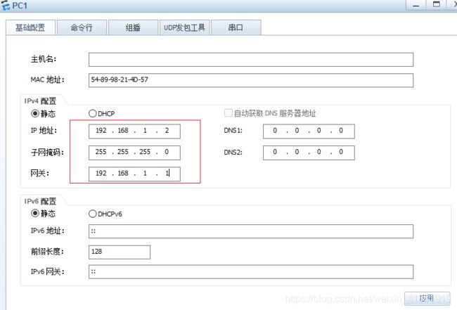
4.配置PC1(配置完成后应用)
4.配置AR2路由器接口信息
[Huawei]sysname R2 重命名路由器名称
[R2]interface Vlanif 1 虚拟交换机接口1
[R2-Vlanif1]ip address 192.168.1.1 24 添加接口信息配置
[R2-Vlanif1]undo ip address 删除添加的接口信息
[R2-Vlanif1]ip address 192.168.1.1 255.255.255.0 也可以添加接口信息配置
[R2-Vlanif1]display this 查看Vlanif1下接口信息配置
[R2-Vlanif1]quit 退出Vlanif1
[R2]interface GigabitEthernet 0/0/0 添加路由另一个出口接口信息配置
[R2-GigabitEthernet0/0/0]ip address 20.1.1.1 24 添加接口信息
[R2]display current-configuration 查看接口的配置信息
The device is running!

sys
system-view
Enter system view, return user view with Ctrl+Z.
[Huawei]sysname R2
[R2]int
[R2]interface vl
[R2]interface Vlanif 1
Apr  6 2020 15:42:53-08:00 R2 %%01IFNET/4/IF_STATE(l)[0]:Interface Vlanif1 has t
urned into UP state.
[R2-Vlanif1]ip add
[R2-Vlanif1]ip address 192.168.1.1 24
[R2-Vlanif1]
Apr  6 2020 15:44:31-08:00 R2 %%01IFNET/4/LINK_STATE(l)[1]:The line protocol IP
on the interface Vlanif1 has entered the UP state.
[R2-Vlanif1]ip address 192.168.1.1 255.255.255.0
Error: The address already exists.
[R2-Vlanif1]undo ip add
[R2-Vlanif1]undo ip address
[R2-Vlanif1]
Apr  6 2020 15:45:20-08:00 R2 %%01IFNET/4/LINK_STATE(l)[2]:The line protocol IP
on the interface Vlanif1 has entered the DOWN state.
[R2-Vlanif1]ip address 192.168.1.1 255.255.255.0
Apr  6 2020 15:45:24-08:00 R2 %%01IFNET/4/LINK_STATE(l)[3]:The line protocol IP
on the interface Vlanif1 has entered the UP state.
[R2-Vlanif1]disp
[R2-Vlanif1]display this
[V200R003C00]
#
interface Vlanif1
 ip address 192.168.1.1 255.255.255.0
#
return
[R2-Vlanif1]quit
[R2]inter
[R2]interface g
[R2]interface GigabitEthernet 0/0/0
[R2-GigabitEthernet0/0/0]ip add
[R2-GigabitEthernet0/0/0]ip address 20.1.1.1 24
Apr  6 2020 15:48:48-08:00 R2 %%01IFNET/4/LINK_STATE(l)[4]:The line protocol IP
on the interface GigabitEthernet0/0/0 has entered the UP state.
[R2-GigabitEthernet0/0/0]display this
[V200R003C00]
#
interface GigabitEthernet0/0/0
 ip address 20.1.1.1 255.255.255.0
#
return
[R2-GigabitEthernet0/0/0]quit
[R2]dis
[R2]display cu
[R2]display current-configuration
[V200R003C00]
#
 sysname R2
#
 snmp-agent local-engineid 800007DB03000000000000
 snmp-agent
#
 clock timezone China-Standard-Time minus 08:00:00
#
portal local-server load portalpage.zip
#
 drop illegal-mac alarm
#
 set cpu-usage threshold 80 restore 75
#
aaa
 authentication-scheme default
 authorization-scheme default
 accounting-scheme default
 domain default
 domain default_admin
 local-user admin password cipher %$%$K8m.Nt84DZ}e#<0`8bmE3Uw}%$%$
 local-user admin service-type http
#
firewall zone Local
 priority 15
#
interface Vlanif1
 ip address 192.168.1.1 255.255.255.0
#
interface Ethernet0/0/0
#
interface Ethernet0/0/1
#
interface Ethernet0/0/2
#
interface Ethernet0/0/3
#
interface Ethernet0/0/4
#
interface Ethernet0/0/5
#
interface Ethernet0/0/6
#
interface Ethernet0/0/7
#
interface GigabitEthernet0/0/0
 ip address 20.1.1.1 255.255.255.0
#
interface GigabitEthernet0/0/1
#
interface NULL0
#
user-interface con 0
 authentication-mode password
user-interface vty 0 4
user-interface vty 16 20
#
wlan ac
#
return
[R2]
查看是否能ping通192.168.1.1网关和PC1地址
return
[R2]

  Please check whether system data has been changed, and save data in time

  Configuration console time out, please press any key to log on

sys
Enter system view, return user view with Ctrl+Z.
[R2]ping 192.168.1.1
  PING 192.168.1.1: 56  data bytes, press CTRL_C to break
    Reply from 192.168.1.1: bytes=56 Sequence=1 ttl=255 time=30 ms
    Reply from 192.168.1.1: bytes=56 Sequence=2 ttl=255 time=1 ms
    Reply from 192.168.1.1: bytes=56 Sequence=3 ttl=255 time=1 ms
    Reply from 192.168.1.1: bytes=56 Sequence=4 ttl=255 time=1 ms

  --- 192.168.1.1 ping statistics ---
    4 packet(s) transmitted
    4 packet(s) received
    0.00% packet loss
    round-trip min/avg/max = 1/8/30 ms

[R2]ping 192.168.1.2
  PING 192.168.1.2: 56  data bytes, press CTRL_C to break
    Reply from 192.168.1.2: bytes=56 Sequence=1 ttl=128 time=90 ms
    Reply from 192.168.1.2: bytes=56 Sequence=2 ttl=128 time=20 ms
    Reply from 192.168.1.2: bytes=56 Sequence=3 ttl=128 time=10 ms
    Reply from 192.168.1.2: bytes=56 Sequence=4 ttl=128 time=20 ms

  --- 192.168.1.2 ping statistics ---
    4 packet(s) transmitted
    4 packet(s) received
    0.00% packet loss
    round-trip min/avg/max = 10/35/90 ms

[R2]
5.配置AR1路由器接口信息,并测试ping
sys
Enter system view, return user view with Ctrl+Z.
[Huawei]sysname R1
[R1]int
[R1]interface g
[R1]interface GigabitEthernet 0/0/0
[R1-GigabitEthernet0/0/0]ip add
[R1-GigabitEthernet0/0/0]ip address 20.1.1.2 24
Apr  6 2020 16:04:29-08:00 R1 %%01IFNET/4/LINK_STATE(l)[0]:The line protocol IP
on the interface GigabitEthernet0/0/0 has entered the UP state.
[R1-GigabitEthernet0/0/0]quit
[R1]interface GigabitEthernet 0/0/1
[R1-GigabitEthernet0/0/1]ip address 20.1.2.2 24
Apr  6 2020 16:04:57-08:00 R1 %%01IFNET/4/LINK_STATE(l)[1]:The line protocol IP
on the interface GigabitEthernet0/0/1 has entered the UP state.
[R1-GigabitEthernet0/0/1]ping 20.1.1.1
  PING 20.1.1.1: 56  data bytes, press CTRL_C to break
    Reply from 20.1.1.1: bytes=56 Sequence=1 ttl=255 time=110 ms
    Reply from 20.1.1.1: bytes=56 Sequence=2 ttl=255 time=20 ms
    Reply from 20.1.1.1: bytes=56 Sequence=3 ttl=255 time=10 ms
    Reply from 20.1.1.1: bytes=56 Sequence=4 ttl=255 time=20 ms
    Reply from 20.1.1.1: bytes=56 Sequence=5 ttl=255 time=20 ms

  --- 20.1.1.1 ping statistics ---
    5 packet(s) transmitted
    5 packet(s) received
    0.00% packet loss
    round-trip min/avg/max = 10/36/110 ms

[R1-GigabitEthernet0/0/1]
6.配置AR3路由器接口信息,并测试ping
sys
Enter system view, return user view with Ctrl+Z.
[Huawei]sysname R3
[R3]sysname Huawei
[Huawei]sysname R3
[R3]inte
[R3]interface g
[R3]interface GigabitEthernet 0/0/1
[R3-GigabitEthernet0/0/1]ip add
[R3-GigabitEthernet0/0/1]ip address 20.1.2.1 24
[R3-GigabitEthernet0/0/1]quit
[R3]inter
[R3]interface vl
[R3]interface Vlanif 1
Apr  6 2020 16:09:34-08:00 R3 %%01IFNET/4/IF_STATE(l)[0]:Interface Vlanif1 has t
urned into UP state.
[R3-Vlanif1]ip add
[R3-Vlanif1]ip address 192.168.2.1 24
Apr  6 2020 16:10:05-08:00 R3 %%01IFNET/4/LINK_STATE(l)[1]:The line protocol IP
on the interface Vlanif1 has entered the UP state.
[R3-Vlanif1]ping 20.1.2.2
  PING 20.1.2.2: 56  data bytes, press CTRL_C to break
    Reply from 20.1.2.2: bytes=56 Sequence=1 ttl=255 time=90 ms
    Reply from 20.1.2.2: bytes=56 Sequence=2 ttl=255 time=20 ms
    Reply from 20.1.2.2: bytes=56 Sequence=3 ttl=255 time=30 ms
    Reply from 20.1.2.2: bytes=56 Sequence=4 ttl=255 time=30 ms
    Reply from 20.1.2.2: bytes=56 Sequence=5 ttl=255 time=30 ms

  --- 20.1.2.2 ping statistics ---
    5 packet(s) transmitted
    5 packet(s) received
    0.00% packet loss
    round-trip min/avg/max = 20/40/90 ms
[R3-Vlanif1]ping 192.168.2.1
  PING 192.168.2.1: 56  data bytes, press CTRL_C to break
    Reply from 192.168.2.1: bytes=56 Sequence=1 ttl=255 time=20 ms
    Reply from 192.168.2.1: bytes=56 Sequence=2 ttl=255 time=1 ms
    Reply from 192.168.2.1: bytes=56 Sequence=3 ttl=255 time=1 ms
    Reply from 192.168.2.1: bytes=56 Sequence=4 ttl=255 time=1 ms
    Reply from 192.168.2.1: bytes=56 Sequence=5 ttl=255 time=1 ms

  --- 192.168.2.1 ping statistics ---
    5 packet(s) transmitted
    5 packet(s) received
    0.00% packet loss
    round-trip min/avg/max = 1/4/20 ms
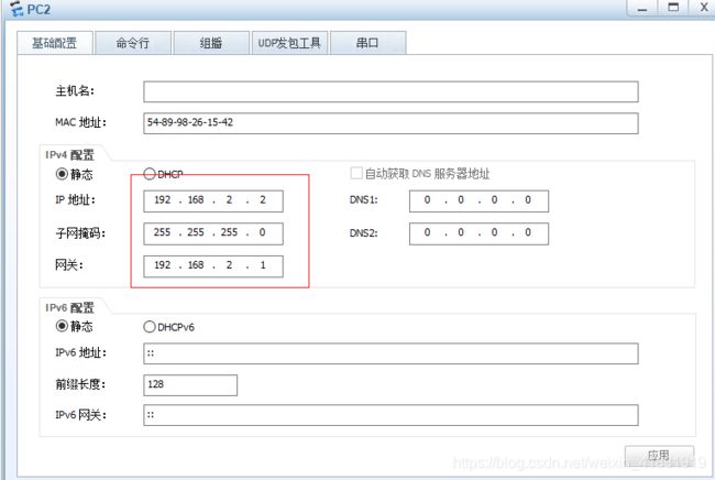
7.配置PC1(配置完成后应用)
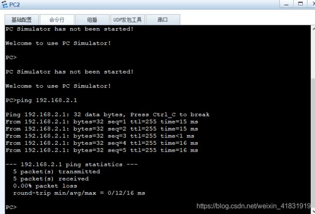
测试PC2端能否ping通网关
接下来就是重点,打通到目的地的路由线路(1网络畅通的条件是有去又回,配置完成后检查是否ping通各个目的地 2路由器默认的只有直连的网段,没有直连的需要管理员添加,这也是现在接下来要做的)
8.配置AR2路由信息表
[R2]display ip routing-table 查看路由表信息配置
[R2]ip route-static 20.1.2.0 24 20.1.1.2 添加到20.1.2.0的网段配置
[R2]ip route-static 192.168.2.0 24 20.1.1.2 添加到192.168.2.0的网段配置
[R2]display ip routing-table 查看显示变化后的路由表信息配置
sys
Enter system view, return user view with Ctrl+Z.
[R2]dis
[R2]display ip ro
[R2]display ip routing-table
Route Flags: R - relay, D - download to fib
------------------------------------------------------------------------------
Routing Tables: Public
         Destinations : 10       Routes : 10

Destination/Mask    Proto   Pre  Cost      Flags NextHop         Interface

       20.1.1.0/24  Direct  0    0           D   20.1.1.1        GigabitEthernet
0/0/0
       20.1.1.1/32  Direct  0    0           D   127.0.0.1       GigabitEthernet
0/0/0
     20.1.1.255/32  Direct  0    0           D   127.0.0.1       GigabitEthernet
0/0/0
      127.0.0.0/8   Direct  0    0           D   127.0.0.1       InLoopBack0
      127.0.0.1/32  Direct  0    0           D   127.0.0.1       InLoopBack0
127.255.255.255/32  Direct  0    0           D   127.0.0.1       InLoopBack0
    192.168.1.0/24  Direct  0    0           D   192.168.1.1     Vlanif1
    192.168.1.1/32  Direct  0    0           D   127.0.0.1       Vlanif1
  192.168.1.255/32  Direct  0    0           D   127.0.0.1       Vlanif1
255.255.255.255/32  Direct  0    0           D   127.0.0.1       InLoopBack0

[R2]ip rou
[R2]ip route-s
[R2]ip route-static 20.1.2.0 24 20.1.1.2
[R2]ip route-static 192.168.2.0 24 20.1.1.2
[R2]display ip routing-table
Route Flags: R - relay, D - download to fib
------------------------------------------------------------------------------
Routing Tables: Public
         Destinations : 12       Routes : 12

Destination/Mask    Proto   Pre  Cost      Flags NextHop         Interface

       20.1.1.0/24  Direct  0    0           D   20.1.1.1        GigabitEthernet
0/0/0
       20.1.1.1/32  Direct  0    0           D   127.0.0.1       GigabitEthernet
0/0/0
     20.1.1.255/32  Direct  0    0           D   127.0.0.1       GigabitEthernet
0/0/0
       20.1.2.0/24  Static  60   0          RD   20.1.1.2        GigabitEthernet
0/0/0
      127.0.0.0/8   Direct  0    0           D   127.0.0.1       InLoopBack0
      127.0.0.1/32  Direct  0    0           D   127.0.0.1       InLoopBack0
127.255.255.255/32  Direct  0    0           D   127.0.0.1       InLoopBack0
    192.168.1.0/24  Direct  0    0           D   192.168.1.1     Vlanif1
    192.168.1.1/32  Direct  0    0           D   127.0.0.1       Vlanif1
  192.168.1.255/32  Direct  0    0           D   127.0.0.1       Vlanif1
    192.168.2.0/24  Static  60   0          RD   20.1.1.2        GigabitEthernet
0/0/0
255.255.255.255/32  Direct  0    0           D   127.0.0.1       InLoopBack0

[R2]
9.配置AR1路由信息表
sys
Enter system view, return user view with Ctrl+Z.
[R1]ip rou
[R1]ip route-s
[R1]ip route-static 192.168.1.0 24 20.1.1.1
[R1]ip route-static 192.168.2.0 24 20.1.2.1
[R1]
10.配置AR3路由信息表
sys
Enter system view, return user view with Ctrl+Z.
[R3]ip rou
[R3]ip route-s
[R3]ip route-static 20.1.1.0 24 20.1.2.2
[R3]ip route-static 192.168.1.0 24 20.1.2.2
[R3]
11.现在所有配置已经完成,测试使用PC1ping PC2的结果
简单的路由信息拓扑打通完成!!!


