Adding RF 433MHz to your Arduino
Adding RF 433MHz to your Arduino
In this tutorial I'll show you how to add RF 433MHz to your Arduino, allowing you to:
- Use your Arduino as a wireless sensor that you can see on your Dashboard
- Use your Arduino as a wireless actuator that you can control from your Dashboard
Ideally, you'll use two Arduini (In Italian, the plural of 'o' is 'i') with one connected to a transmitter and one to a receiver, but if you only have one Arduino, you'll need to re-upload the various provided sketches, or else merge them into one sketch.
If you're only interested in transmitting or receiving, that's no problem, as the Ninja Block has both of these functions built in, and you can use it via the Dashboard to both send are detect the receipt of RF signals.
Let us Away!
Requirements
- An Arduino, or if you're a true Ninja, two Arduini.
- Some RF 433MHz Modules (transmitter and receiver).
- A Ninja block and account.
- Some electronics to attach to your Arduino
- The Code! You'll find that here: https://github.com/ninjablocks/433Utils
If you have git installed you can:
git clone git://github.com/ninjablocks/433Utils.git
Phase One - Install the Hardware
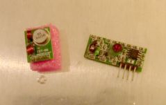
Here are the modules. That's the transmitter on the left, and the receiver is on the right.
Here is a schematic of the modules, courtesy of Seeed Studio (from whom the modules you see here were procured.) :
Make 100% sure you understand the pin layouts- for example, even though if you hold the transmitter as shown in the schematic, you'll actually be looking at the back of the board, you can ensure you've got things right by verifiying that GND is at the outmost end of the board. (It will also be connected to the ground plane)
Step One - Install the Transmitter module
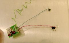
The requirements for this module are easily satisfied. Provide it with power and a data signal, and optionally an antenna, and it's well happy.
I used wire-wrapping techniques to connect mine. You'll see that I've attached the other end of the wires to pin headers that can be plugged into my Arduino.
You can also do this:
It works because we use two of the Arduino's digital pins to provide power. Note- it is a hack of the rankest order- use the 5V and GND pins for power if you can.
In either case the pin you connect the data line of the transmitter to is important, I've used pin 7.
Step Two - Install the Receiver Module
The requirements for this module are the same as for the transmitter, however there are some pin differences, so don't be caught out by this. The two middlemost pins are both data pins, and there is an entirely different area on the board to which to attach an antenna.
Again, I used wire-wrapping techniques to connect mine:
Connect the data pin to Arduino pin 2.
Phase Two - Run the provided Software
You'll find lots of goodies in the RFUtils distribution. The goodies you're interested in for this tutorial are found in the 'Arduino_Sketches' folder.
- RF_Sniffer : A handy RF code reporting Sketch
- Sanity Checks : A folder with two Sketches:
- Receiver : Low level LED blinking receiver tester; no codes, just 'yes I'm receiving data via my receiver's data pin'.
- Sender: Low level data pulser- sends a steady pulse to the transmitter's data pin
- Send_Demo : A simple RF code sender Sketch- sends a code of your choosing every 5 seconds.
- Servo_Receive_Demo : A Sketch that actuates hardware attached to your Arduino based on received RF codes.
Step One - Run the RF_Sniffer Sketch
Look in the 'Arduino Sketches' folder within the code you downloaded from github and open the RF_Sniffer Sketch. Upload it to your Arduino (Ensuring you've installed the receiver module) and after it's finished uploading, open the Serial Monitor.
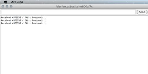
Now grab the wireless button that came with your 433 kit (or any other wireless sensor that is easy to trigger) and press it. You should see something like this appear in your terminal:
This is the RF_Sniffer's primary use- to report on the numeric codes it receives. One you know those codes you can send them from the transmitter and it will be as though you pressed the button! (Or opened the door, etc.)
In fact, we are only just scratching the surface here- using codes of your own design (being careful not to collide with any others of course) you can establish channels of comunnication between devices. You'll see an application of this later on when we command a 2 axis servo mount to pan and tilt.
If you don't have any wirelss transmitting hardware handy, just use the Dashboard, Luke! (Even if that doesn't happen to be your name.)
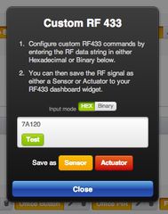
Use your connected actuators to send signals, or if you don't want to actually give your actuators commands, use the custom RF tool to send some new codes. Here- try HEX 7A120 - it's unlikely to be used already, and in fact we will use that code later in the tutorial.
Step Two - Run the Send_Demo Sketch
Use the Arduino with the transmitter attached. Open the Send_Demo Sketch.
Look at the top of the file and you'll see:
#define CODE_Button 4575536 // Use whatever number you saw in the RF Sniffer Sketch
Change that number to match the number you saw when you ran the RF_Sniffer Sketch.
Upload it to your Arduino (Ensuring you've installed the transmitter module) and after it's finished uploading, use your Dashboard to monitor the incoming RF signals by using the 'Listen' function. (This is something I'm encouraging my 5 year old son to do all the time)
What this demonstrates is that you are now able to emulate any of the RF sensors by using their code. This means for instance that you could toggle a Watts Clever Socket Actuator from your Arduino. All you need to do is use your Arduno RF_Sniffer Sketch to find the code it generates. You can use the Dashboard for this purpose as well, but bear in mind it will only report the codes that are known to the platform so far. You can use the RF_Sniffer sketch as a lower-level sanity check that RF signals are being sent by your sensor.
Step Three - Run the Servo_Receive_Demo Sketch
The purpose of this sketch is to demonstrate the control of a 2 axis servo motor via your Dashboard. You can trivially substitute pretty much any actuator for the servos.
You'll notice in the sketch that I've defined codes for servo control at the top of the file. I've chosen those numbers fairly arbitrarily (they don't conflict with any other devices.
Use the Arduino with the receiver attached. Open the Servo_Receive_Demo Sketch. Upload it to your Arduino.
Go to your Ninja Dashboard:
Choose 'Listen'
Enter the HEX codes for servo control into the field and press 'Test'. Your servo should tilt up. Press 'Actuator' and name it 'Servo Up'.
Repeat this process for all the servo codes. (They are provided in the sketch.)
Voila! You now have control of your wireless contraption via your Ninja Dashboard!
Now let's look at receiving sensor data on your Ninja Dashboard.
Step Four - Modify the Send_Demo Sketch to act as a sensor.
We'll create a simplified variable resistor sensor. Connect a variable resistor to your Arduino like so:
Open the Send_Demo sketch again , and change the line
#define SETTING_UsePot false // Make this true for Step Four of the tutorial.
to
#define SETTING_UsePot true // Make this true for Step Four of the tutorial.
Compile and upload the sketch to the Arduino with the transmitter.
Open your Dashboard and again, use the 'Listen' function. Turn your pot's knob all the way to the left and wait for an RF code to appear. When you're sure that this is the code that the Arduino is sending (You'll see the number next to the code increment every 5 seconds.) then press 'sensor' and name the sensor 'Pot Left'.
Turn the pot's knob to roughly in the middle, and repeat the process, naming the sensor 'Pot Mid'.
Turn the pot's knob all the way to the right, and repeat the process, naming the sensor 'Pot Right'.
You can do these even more quickly with the 'Use custom RF' function, and enter the HEX codes directly. (They are provided in the sketch).
Here are those codes, correctly received by the Ninja Dashboard:
If you need this data to arrive at your Dashboard more often, you can decrease the delay from 5 seconds, but be aware that sending RF data too often will cause issues.
Conclusion
With these elements in place, it's possible to incorporate your new sensors and actuators into your Rules as you would any other!
Here are some simple examples:
- Light Nina's eyes different colours based on the value of the pot. Remember, you can substitute any variable resistor for the pot- for example a strain meter or a light sensor.
- Turn your servo rig with a web cam riding on top to its home position (pointing at your door) when your door sensor is triggered.
- Switch a relay on that lights up a sign that says "Marry Me" when a webhook is triggered by getting a certain number of views on YouTube.
Do let us know what you come up with, as well as any errors you encounter in this tutorial or accompanying code.
Stay Ninja!


