合肥工业大学 硬件工程师综合训练 旋转图形设计
目录
- 一、 课程设计题目及要求
- 二、课程设计任务与目标
-
- 1、实验原理
- 2、实验过程
- 三、设计框图
- 四、硬件实现原理
- 五、硬件实现和演示结果
- 六、收获、不足和下一步改进方法
- 七、附录:实验代码
一、 课程设计题目及要求
设计题目:“【课题16】 旋转图形设计”
设计要求: 了解旋转图形如何呈现的原理;加深了解控制在实际中的应用。
二、课程设计任务与目标
1、实验原理
一个旋转中的图形,当每转到一定角度时,被照亮一下,不断重复此过程,就可以看到图形稳定的图像(虽然该图形在旋转中)。如果推迟照亮(推迟时间很短),就会出现图形在慢慢旋转。
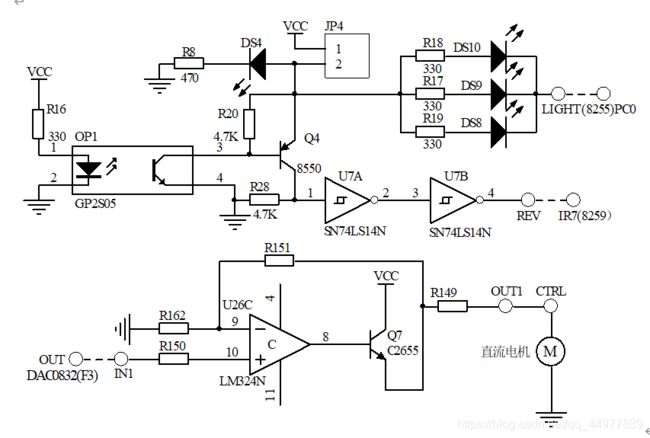
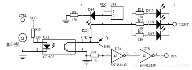
本实验利用光电开关来判断转盘转到某个固定角度的时刻,给出中断信号
2、实验过程
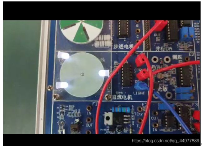
(1)由光电开关结合中断给出控制信号,通过CPU控制直流电机边上的小灯闪烁,将直流电机驱动的旋转转盘上的图形呈现出来,并令图形也在旋转(缓慢的)。
三、设计框图
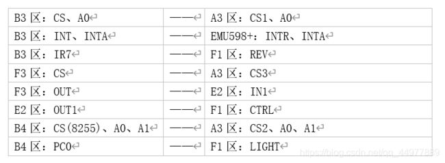
实物连线如下
四、硬件实现原理
- A3区:CPU总线、片选区
JP45:地址线A0-A7; JP48、JP50:地位地址/数据总线:JP51、JP55:MCS51的P1口;JP59:高位地址线A8-A15; JP61,JP64: MCS51的P3口,P3.7,P3.6作读写信号线;JP66:相当于一个MCS51类的cpu座,使用40芯扁线与用户板相连,可仿真P0,P2口作地址、数据使用的MCS51类CPU。
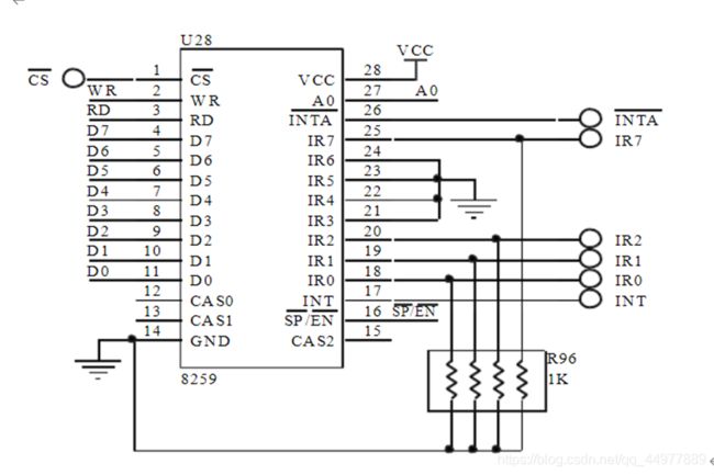
CS:片选信号,低电平有效;A0:地址信号;INR0-INR7:中断输入;INTA:中断响应
CS:片选信号,低电平有效;A0,A1:地址信号; JP52:PC口
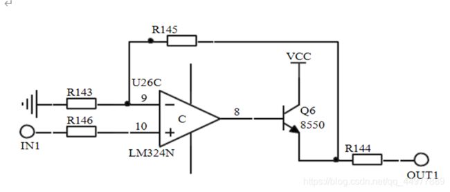
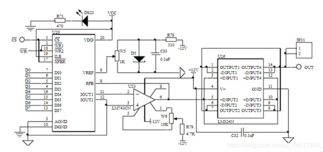
- E2区:PWM电压转换
IN1:信号输入; OUT1:信号输出。
CTRL:控制电压输入;
REV:光电开关或霍尔器件输出(用于转速测量);LIGHT:低电平点亮发光管
CS:片选,低电平有效;OUT:转换电压输出。
五、硬件实现和演示结果
六、收获、不足和下一步改进方法
七、附录:实验代码
.MODEL SMALL
IO8259_0 equ 0250h
IO8259_1 equ 0251h
IO8255_Con equ 0263h
IO8255_PC EQU 0262H ;light is in PC0
vol equ 42h
dac0832_add equ 0d00h
.stack 100
.data
count dw 0
flashflag db 0
speed2 dw 20
gap dw 0
.code
start:
mov ax,@data
mov ds,ax
mov es,ax
mov count,1
mov flashflag,0
call Init8255
call init8259
nop
nop
set_int_vector:
push ax
push es
push bx
mov ax,0
mov es,ax
mov bx,60
mov ax,offset int_led
mov es:[bx],ax
mov ax,seg int_led
mov es:[bx+2], ax
pop bx
pop es
pop ax
set_int_vector_done:
nop
nop
call dac0832
main:
sti
cmp flashflag,0
cli
jz main
mov flashflag,0
call flashled;BP here
jmp main
nop
nop
int 3h
int_led:
cli
push ax
push dx
mov flashflag,1
mov dx,IO8259_0
mov al,20h
out dx,al
pop dx
pop ax
sti
iret
flashled proc near
;cli
call delayled
mov dx,IO8255_PC
mov al,0
out dx,al; BP here
mov dx,IO8255_Con
mov al,0
out dx,al; BP here
call delaytime
mov dx,IO8255_PC
mov al,0ffh
out dx,al; BP here
mov dx,IO8255_Con
mov al,01h
out dx,al; BP here
;sti
ret
flashled endp
delayled proc near
mov cx,count
seg1@delayled:
call delay
loop seg1@delayled
inc count
mov ax,count
cmp ax,200 ;change it to change speed/sense of rotation
jnz endseg@delayled
mov count,1
endseg@delayled:
ret
delayled endp
delay proc near
push cx
mov cx,2 ;change it to change led flash time or sense of rotation
loop \$
pop cx
ret
delay endp
;time of led flashing
delaytime proc near
push cx
mov cx,speed2
loop \$
mov cx,speed2
cmp cx,120
jb adder@delaytime
jmp notadd@delaytime
adder@delaytime:
add cx,1
mov speed2,cx
mov cx,0
mov gap,cx
notadd@delaytime:
pop cx
ret
delaytime endp
init8259 proc near
mov dx,IO8259_0
mov al,13h ;ICW1
out dx,al
mov dx,IO8259_1
mov al,08h; Should be ICW2
;IR7 should be in 0FH
out dx,al
;No need any ICW3
mov dx,IO8259_1
mov al,09h
out dx,al
;OCW1
mov al,7FH
out dx,al
ret
init8259 endp
dac0832 proc near
mov dx,dac0832_add
mov al,vol
out dx,al
ret
dac0832 endp
Init8255 proc near
push dx
push ax
mov dx,IO8255_Con
mov al,80h
out dx,al
;port test
mov dx,IO8255_Con
mov al, 00h
out dx,al
mov al,01h
out dx,al
;test done
mov al,0ffh
mov dx,IO8255_PC
out dx,al
pop ax
pop dx
ret
Init8255 endp
end start
既来之,则赞之
若有疑问,创所欲言
