verilog学习:使用VCS仿真验证一个全加器
前言:
- 之前的文章《verilog学习:一个简单的入门verilog例子》,给了一个简单的verilog例子,今天找个实例使用Linux下的VCS、dve工具仿真一下,给初学者了解一下
- (不希望初学者能直接看懂,在往后的学习中会逐渐懂就够了)。
- 这篇文章提到的例子,好像是E课网上课讲过的例子,大家可以去之前的文章《IC前端数字验证导学》找到对应的视频链接去学习。
1.design
全加器的设计代码见下:
//full_adder.v

module full_adder(
//module head; verilog-2001 format
input wire a_in,
input wire b_in,
input wire c_in,//carry in
output wire sum_out,
output wire c_out//carrry out
);

//method 1 Gate Level describe
assign sum_out = a_in^b_in^c_in;
assign c_out =(a_in & b_in)|(b_in & c_in)|(a_in&c_in);

//method2 RTL design for Adder with the keyword "assign"
//behavior of the adder can be synthesizable
//"assign" means connectivity,which is used to describe a combinational circuit
//assign {c_out,sum_out} = a_in + b_in + c_in;

//method3 RTL design for Adder with the keyword "always"
//reg c_o,sum_o;
//always@(a_in,b_in,c_in)begin
//{c_o,sum_o} = a_in +b_in +c_in;
//end
//assign {c_out,sum_out}={c_o,sum_o};
endmodule
有了设计,最关心的验证就来了
2.验证tb
验证的代码如下:
//full_adder_tb.v

module full_adder_tb;
//drive the input port wth the reg type
reg ain,bin,cin;
//sample the output port with the wire type
wire sumout,cout;

full_adder u_full_adder(
//task1.how to creat an instance
//module head :verilog_2001 format
.a_in(ain),
.b_in(bin),
.c_in(cin),
.sum_out(sumout),
.c_out(cout)
);

//task2 clock and reset generator
parameter CLK_PERIOD = 20;
reg clk,reset_n;//reset_n:active low

initial begin
  clk = 0 ;
  forever begin
    #(CLK_PERIOD/2) clk =~clk;
  end
end

initial begin
  reset_n = 0;
  #100
  reset_n = 1;
end

//task3.drive the stimulus and capture the response
//here is a testcase
initial begin
  #110 ain = 0; bin = 0;cin = 0;//00
  #20  ain = 0; bin = 1;cin = 0;//01
  #20  ain = 1; bin = 0;cin = 0;//01
  #20  ain = 1; bin = 1;cin = 0;//10
  #20  ain = 0; bin = 0;cin = 1;//01
  #20  ain = 0; bin = 1;cin = 1;//10
  #20  ain = 1; bin = 0;cin = 1;//10
  #20  ain = 1; bin = 1;cin = 1;//11
  //#20  ain = 1; bin = 1;cin = 0;//10
  #50 $finish;//here is a system task which can stop the stimulation
end

//task4.check the result
always@(posedge clk)begin
  if(!reset_n)begin
    $display("%t:%m:resetting...",$time);//counter 5 clock
  end
  else begin
    $display("%t:%m:resetting finish !",$time);//the 6th clock
  end
end

initial begin
  #115 if({
     cout,sumout}!=2'b00)$display("Error:{cout,sumout}=%b,ain=%b,cin=%b",{
     cout,sumout},ain,bin,cin);
  #20  if({
     cout,sumout}!=2'b01)$display("Error:{cout,sumout}=%b,ain=%b,cin=%b",{
     cout,sumout},ain,bin,cin);
  #20  if({
     cout,sumout}!=2'b01)$display("Error:{cout,sumout}=%b,ain=%b,cin=%b",{
     cout,sumout},ain,bin,cin);
  #20  if({
     cout,sumout}!=2'b10)$display("Error:{cout,sumout}=%b,ain=%b,cin=%b",{
     cout,sumout},ain,bin,cin);
  #20  if({
     cout,sumout}!=2'b01)$display("Error:{cout,sumout}=%b,ain=%b,cin=%b",{
     cout,sumout},ain,bin,cin);
  #20  if({
     cout,sumout}!=2'b10)$display("Error:{cout,sumout}=%b,ain=%b,cin=%b",{
     cout,sumout},ain,bin,cin);
  #20  if({
     cout,sumout}!=2'b11)$display("Error:{cout,sumout}=%b,ain=%b,cin=%b",{
     cout,sumout},ain,bin,cin);
  #20  if({
     cout,sumout}!=2'b10)$display("Error:{cout,sumout}=%b,ain=%b,cin=%b",{
     cout,sumout},ain,bin,cin);
end

//task5.dump waveform with the compile option -debug_all
initial begin
  $vcdpluson;
end
endmodule
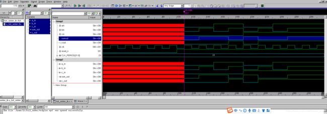
3.编译仿真看波形
- 本来是想试一下调用下面的Makefile.questasim脚本文件操作
//Makefile.questasim

all: create_lib compile simulate

create_lib:
	vlib work

compile:
	vlog -l com.log ./full_adder.v ./full_adder_top.v

simulate:
	vsim -l sim.log -c -novopt full_adder_tb -do "log -r*"; run -all;quit -f"

clean:
	rm -rf work mti_lib transcript modelsim.ini *.log vsim.wlf
那就使用最原始的输入命令的方式进行仿真:
编译:
vcs *.v -l com.log +v2k -debug_pp +vcd+vcdpluson
仿真:
./simv -l sim.log
看波形:
dve –vpd vcdpluson.vpd
- 初学者刚开始会使用前面这种代码仿真就可以了,当学到一定高度时,你会了解到各种脚本帮你简化操作,例如:下面的这种Makefile脚本就可以简化仿真输入。
- 用vcs仿真的脚本贴在下面,希望对大家有用:
#Makefile for full_adder

all:clean compile simulate

compile:
	vcs -debug_all -l compile.log full_adder.v full_adder_tb.v

simulate:
	./simv -l simulate.log

compile_coverage:
	vcs -debug_all -cm line+cond+fsm+tgl+branch -lca -l compile.log full_adder.v full_adder_tb.v

simulate_coverage:
	./simv -cm line+cond+fsm+tgl+branch -lca -l simulate.log

report_cov:
	urg -dir simv.vdb -format both -report coverage

dve_cov:
	dve -cov -covdir simv.vdb -lca

clean:
	rm -rf *.log csrc DVEfiles simv simv.daidir ucli.key vcdplus.vpd
后记
- 查看往期文章,请点击跳转
《IC前端数字验证导学》
《如何学习verilog,如何快速入门?》
《verilog学习:一个简单的入门verilog例子》 - 如需长期追更,可以扫码关注下面这个公众号


