鄙系有一门很著名的课,《计算机组成原理》,教你三周造台计算机。我们组今年眼瞎,选了挑战性课程,也就是教你一学期造台32位MIPS架构的计算机。前段时间全组人都被软工和编译原理所困扰(实际上,今天是编译原理第二次大作业的deadline,但我还没做完,但是我仍然在这里悠闲地写文章……),因此并未开始,直到昨天(第八周的周五)才开始研究软件的基本使用……
研究之后决定,主要仿照《自己动手写CPU》这本书的结构来进行编写和仿真。今天暂且先进行PC模块的简单实现和仿真。
参考文献
- 自己动手写处理器之第二阶段(4)——电路设计举例
- 自己动手写处理器之第二阶段(5)——ModelSim电路仿真
- Xilinx Vivado的使用详细介绍(1):创建工程、编写代码、行为仿真、Testbench
- 无数eda论坛和stackoverflow上的帖子
硬件和编译软件
我们使用的FPGA芯片是Xlinx的,具体型号是:Xilinx Artix-7系列FPGA: XC7A100TFGG676-2L,对应的编译软件是Xlinx的Vivado v2017.1 (64-bit)(当然,某些别的版本和平台的Vivado应该也可以)。
Vivado的详细使用方法可以参见这篇文章,虽然讲的是Verilog语言的编写和测试方法,但是VHDL也差不多。
简单PC模块的实现
完整代码的git仓库见这里。
这一部分的代码基本翻译自《自己动手写CPU》的2.7-2.8节,原文请参见书或作者专栏。
pc_reg.vhd
这一部分的实现十分简单,只需要在clk的上升沿给出ce的值,并且在使能的时候不断增加pc的值即可。需要注意的是,和Verilog不同,VHDL不能读输出端口的值,所以需要增加一个signal。
library IEEE;
use IEEE.STD_LOGIC_1164.ALL;
use IEEE.STD_LOGIC_SIGNED.ALL;

entity pc_reg is
    Port ( rst : in STD_LOGIC;
           clk : in STD_LOGIC;
           pc : out STD_LOGIC_VECTOR(5 downto 0);
           ce : out STD_LOGIC);
end pc_reg;

architecture Behavioral of pc_reg is
    signal ce_o : STD_LOGIC;
    signal pc_o : STD_LOGIC_VECTOR(5 downto 0);

begin

    process (clk'event)
    begin
        if rising_edge(clk) then
            if rst = '1' then
                ce <= '0';
                ce_o <= '0';
            else
                ce <= '1';
                ce_o <= '1';
            end if;
        end if;
    end process;

    process (clk'event)
        begin
            if rising_edge(clk) then
                if ce_o = '0' then
                    pc <= b"000000";
                    pc_o <= b"000000";
                else
                    pc_o <= pc_o + b"000001";  -- STD_LOGIC_SIGNED library
                    pc <= pc_o;
                end if;
            end if;
        end process;

end Behavioral;
rom.vhd
为了实现VHDL在模拟时读取文件数据,在这里debug了好久……显然VHDL比Verilog麻烦得多。花了好久才找到从文件读16进制数据后转换成STD_LOGIC_VECTOR的方法。
library IEEE;
use IEEE.STD_LOGIC_1164.ALL;
use IEEE.NUMERIC_STD.ALL;
use IEEE.STD_LOGIC_UNSIGNED.ALL;
use STD.TEXTIO.ALL;
use IEEE.STD_LOGIC_TEXTIO.ALL;

entity rom is
    Port ( ce : in STD_LOGIC;
           addr : in STD_LOGIC_VECTOR(5 downto 0);
           inst : out STD_LOGIC_VECTOR(31 downto 0));
end rom;

architecture Behavioral of rom is
begin

    process
    type rom_array_type is array(63 downto 0) of STD_LOGIC_VECTOR(31 downto 0);
    variable rom_array : rom_array_type;
    file filein : text;
    variable fstatus : FILE_OPEN_STATUS;
    variable buf : LINE;
    variable output : LINE;
    variable data : STD_LOGIC_VECTOR(31 downto 0);
    variable index : STD_LOGIC_VECTOR(5 downto 0) := "000000";
    begin
        -- 在process中,先打开文件
        file_open(fstatus, filein, "/home/zhanghuimeng/Computer_Architecture/TestThinpadProject/rom.data", read_mode);
        -- 这里给出的是绝对地址,因为我也不知道如果用相对地址,应该把文件放在哪里……
            while not endfile(filein) loop
                readline(filein, buf);
                -- 正常情况下,endfile(filein)就可以了,但是这里需要单独判断buf有没有读到内容
                -- 否则会报错:Error: STD_LOGIC_ll64.HREAD End of String encountered
                if buf'length = 0 then
                    exit;
                end if;
                hread(buf, data);

                rom_array(to_integer(unsigned(index))) := data;

                -- 打印rom_array(index)的值
                -- 这些并不是必须的,但调试的时候比较方便。
                deallocate(output);
                write(output, string'("rom_array("));
                write(output, integer'(to_integer(unsigned(index))));
                write(output, string'(") = "));
                write(output, rom_array(to_integer(unsigned(index))));
                report output.all;

                index := index + "000001";
            end loop;

        -- 等待ce和addr变化
        -- 正常情况下是写在process的敏感信号中,但此处需要读完rom_array的初始数据后再开始等待
        loop
            wait on ce, addr;
            if (ce = '0') then
                inst <= x"00000000";
            else
                inst <= rom_array(to_integer(unsigned(addr)));
            end if;
        end loop;
    end process;

end Behavioral;
顶层文件inst_fetch.vhd
除了把端口都连起来之外没有什么需要特别注意的。不过,VHDL中,在map端口的时候,属于实体的端口名写在前面,属于顶层文件的端口名和信号名写在后面。
library IEEE;
use IEEE.STD_LOGIC_1164.ALL;

entity inst_fetch is
    Port ( rst : in STD_LOGIC;
           clk : in STD_LOGIC;
           inst_o : out STD_LOGIC_VECTOR(31 downto 0));
end inst_fetch;

architecture Behavioral of inst_fetch is

component pc_reg
Port ( rst : in STD_LOGIC;
       clk : in STD_LOGIC;
       pc : out STD_LOGIC_VECTOR(5 downto 0);
       ce : out STD_LOGIC);
end component;

component rom is
    Port ( ce : in STD_LOGIC;
           addr : in STD_LOGIC_VECTOR(5 downto 0);
           inst : out STD_LOGIC_VECTOR(31 downto 0));
end component;

signal pc_to_addr : STD_LOGIC_VECTOR(5 downto 0);
signal ce_to_ce : STD_LOGIC;

begin
    pc_reg_0: pc_reg port map(rst => rst, clk => clk, pc => pc_to_addr, ce => ce_to_ce);
    rom_0: rom port map(ce => ce_to_ce, addr => pc_to_addr, inst => inst_o);
end Behavioral;
建立Testbench和仿真
仿真文件rom.data
00000000
01010101
02020202
03030303
04040404
05050505
...
仿真文件inst_fetch_testbench.v
因为VHDL写起来太过麻烦所以就直接用Verilog写(抄)《自己动手写CPU》了。(Vivado仿真器支持VHDL和Verilog的混合使用,详情见Vivado 仿真器— 使用混合语言仿真)
`timescale 1ns / 1ps

module inst_fetch_testbench;
    reg clk;
    reg rst;
    wire[31:0] inst;

    initial begin
        clk = 1'b0;
        forever #10 clk = ~clk;
    end

    initial begin
        rst = 1'b1;
        #195 rst = 1'b0;
        #1000 $stop;
    end

    inst_fetch inst_fetch_0(
        .clk(clk),
        .rst(rst),
        .inst_o(inst)
    );
endmodule
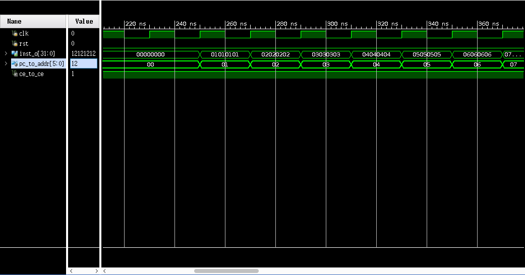
Behavioral Simulation 结果
这说明实现是正确的。

