Real-Time Rendering——4.7.2 Perspective Projection 透视投影
Here, parallel lines are generally not parallel after projection; rather, they may converge to a single point at their extreme. Perspective more closely matches how we perceive the world, i.e.,objects farther away are smaller.
这里平行线一般投影后不平行;相反,它们可能会在极端情况下汇聚到一点。透视更符合我们感知世界的方式,即物体越远越小。
First, we shall present an instructive derivation for a perspective projection matrix that projects onto a plane z = −d, d > 0.We derive from world space to simplify understanding of how the world-to-view conversion proceeds. This derivation is followed by the more conventional matrices used in, for example, OpenGL
首先,我们将给出投影到平面z = -d,d > 0上的透视投影矩阵的有益推导。我们从世界空间中导出,以简化对世界到视图转换如何进行的理解。这个推导之后是在例如OpenGL中使用的更传统的矩阵
Assume that the camera (viewpoint) is located at the origin, and that we want to project a point, p, onto the plane z = −d, d > 0, yielding a new point q = (qx, qy,−d).This scenario is depicted in Figure 4.19. From the similar triangles shown in this figure,the following derivation, for the x-component of q, is obtained:
假设摄像机(视点)位于原点,我们想要将点p投影到平面z = -d,d > 0上,产生一个新点q = (qx,qy,-d)。这种情况如图4.19所示。从该图中所示的类似三角形中,对于q的x分量,获得以下推导:
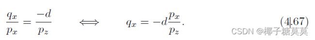
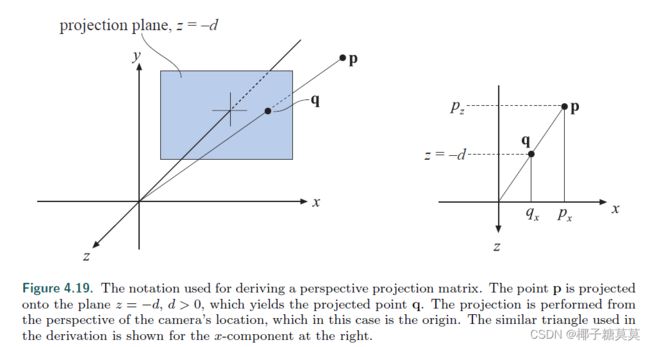
Figure 4.19. The notation used for deriving a perspective projection matrix. The point p is projected onto the plane z = −d, d > 0, which yields the projected point q. The projection is performed from the perspective of the camera’s location, which in this case is the origin. The similar triangle used in the derivation is shown for the x-component at the right.
图4.19。用于导出透视投影矩阵的符号。点p被投影到平面z = d,d > 0,这就产生了投影点q,投影是从摄像机位置的角度进行的,在这种情况下,摄像机位置就是原点。用于推导的类似三角形显示在右侧的x分量上。
The expressions for the other components of q are qy = −dpy/pz (obtained similarly to qx), and qz = −d. Together with the above formula, these give us the perspective projection matrix, Pp, as shown here:
q的其他分量的表达式为Qy = -dpy/pz(与qx类似获得)和qz = -d,加上上述公式,我们得到透视投影矩阵Pp,如下所示:

That this matrix yields the correct perspective projection is confirmed by
这个矩阵产生了正确的透视投影,这一点通过下式得到证实
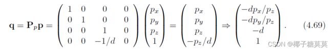
The last step comes from the fact that the whole vector is divided by the w-component (in this case −pz/d), to get a 1 in the last position. The resulting z value is always −d since we are projecting onto this plane.
最后一步是将整个矢量除以w分量(本例中为-Pz/d),从而在最后一位得到1。由于我们投影到这个平面上,因此z值始终为d。
Intuitively, it is easy to understand why homogeneous coordinates allow for projection.One geometrical interpretation of the homogenization process is that it projects the point (px, py, pz) onto the plane w = 1.
直观上,很容易理解为什么齐次坐标允许投影。均匀化过程的一个几何解释是它将点(px,py,pz)投影到平面w = 1上。
As with the orthographic transformation, there is also a perspective transform that, rather than actually projecting onto a plane (which is noninvertible), transforms the view frustum into the canonical view volume described previously. Here the view frustum is assumed to start at z = n and end at z = f, with 0 > n > f. The rectangle at z = n has the minimum corner at (l, b, n) and the maximum corner at (r, t, n). This is shown in Figure 4.20.
与正交变换一样,还有一种透视变换,它不是实际投影到一个平面上(这是不可逆的),而是将视锥体变换为前面描述的标准视景体。这里假设视锥体从z = n开始,到z = f结束,0 > n > f。z = n处的矩形在(l,b,n)处具有最小角,在(r,t,n)处具有最大角。这如图4.20所示。

The parameters (l, r, b, t, n, f) determine the view frustum of the camera. The horizontal field of view is determined by the angle between the left and the right planes (determined by l and r) of the frustum.
参数(l,r,b,t,n,f)决定了摄像机的视锥体。水平视野由视锥体的左右平面之间的角度(由l和r决定)决定。
In the same manner, the vertical field of view is determined by the angle between the top and the bottom planes (determined by t and b). The greater the field of view, the more the camera “sees.” Asymmetric frusta can be created by r 6= −l or t 6= −b. Asymmetric frusta are, for example, used
for stereo viewing and for virtual reality (Section 21.2.3).
同样,垂直视场由顶面和底面之间的角度决定(由t和b决定)。视野越大,相机“看”得越多。不对称截面可由r != l或t != b创建。例如,使用不对称截面用于立体观察和虚拟现实(第21.2.3节)。
The field of view is an important factor in providing a sense of the scene. The eye itself has a physical field of view compared to the computer screen.This relationship is
视野是提供场景感的一个重要因素。与计算机屏幕相比,眼睛本身有一个物理视野。这种关系是

where φ is the field of view, w is the width of the object perpendicular to the line of sight, and d is the distance to the object.
其中φ是视野,w是垂直于直线的物体宽度 视线,d是到物体的距离。
Using a narrower field of view compared to the physical setup will lessen the perspective effect, as the viewer will be zoomed in on the scene. Setting a wider field of view will make objects appear distorted (like using a wide angle camera lens),especially near the screen’s edges, and will exaggerate the scale of nearby objects.
与物理设置相比,使用更窄的视野将减少透视效果,因为观察者将放大场景。设置更宽的视野会使对象看起来失真(像使用广角相机镜头),尤其是在屏幕边缘附近,并且会夸大附近对象的比例。
However, a wider field of view gives the viewer a sense that objects are larger and more impressive, and has the advantage of giving the user more information about the surroundings.
然而,更宽的视野给观看者一种物体更大和更令人印象深刻的感觉,并且具有给用户更多关于周围环境的信息的优点。
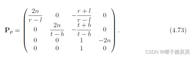
The perspective transform matrix that transforms the frustum into a unit cube is given by Equation 4.71:
将视锥体变换成单位立方体的透视变换矩阵由等式4.71给出:

After applying this transform to a point, we will get another point ![]() .
.
The w-component, qw, of this point will (most often) be nonzero and not equal to one.
To get the projected point, p, we need to divide by qw, i.e.,
将这个变换应用于一个点之后,我们将得到另一个点![]() 该点的w分量qw将(最常见的)非零且不等于1。 为了得到投影点p,我们需要除以qw,即,
该点的w分量qw将(最常见的)非零且不等于1。 为了得到投影点p,我们需要除以qw,即,

The matrix Pp always sees to it that z = f maps to +1 and z = n maps to −1.
矩阵Pp总是确保z = f映射到+1,z = n映射到-1。
Objects beyond the far plane will be clipped and so will not appear in the scene.The perspective projection can handle a far plane taken to infinity, which makes Equation 4.71 become
远平面之外的对象将被剪裁,因此不会出现在场景中。透视投影可以处理被带到无穷远处的远平面,这使得方程4.71变成
To sum up, the perspective transform (in any form), Pp, is applied, followed by clipping and homogenization (division by w), which results in normalized device coordinates.
综上所述,应用透视变换(以任何形式),Pp,随后是裁剪和均匀化(除以w),这导致归一化的设备坐标。
To get the perspective transform used in OpenGL, first multiply with S(1, 1,−1, 1),for the same reasons as for the orthographic transform. This simply negates the values in the third column of Equation 4.71.
要获得OpenGL中使用的透视变换,首先乘以S(1,1,-1,1),原因与正交变换相同。这就简单地给方程4.71第三列中的值乘负。
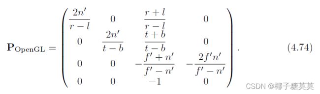
After this mirroring transform has been applied,the near and far values are entered as positive values, with 0 < n′ < f′, as they would traditionally be presented to the user. However, they still represent distances along the world’s negative z-axis, which is the direction of view. For reference purposes, here is the OpenGL equation:
在应用了该镜像变换之后,近值和远值被输入为正值,0 < n′< f′,因为它们通常会被呈现给用户。但是,它们仍然表示沿世界负z轴的距离,这是视图的方向。作为参考,以下是OpenGL公式:
A simpler setup is to provide just the vertical field of view, φ, the aspect ratio a = w/h(where w × h is the screen resolution), n′, and f′. This results in
更简单的设置是只提供垂直视场φ、纵横比a = w/h(其中w × h是屏幕分辨率)、n’和f’。这导致
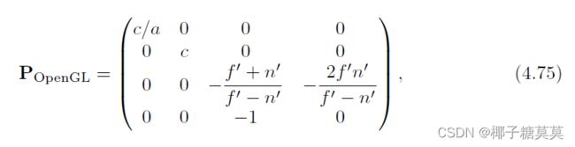
where c = 1.0/ tan(φ/2). This matrix does exactly what the old gluPerspective() did, which is part of the OpenGL Utility Library (GLU).
其中c = 1.0/ tan(φ/2)。这个矩阵做的正是旧的gluPerspective()所做的,它是OpenGL实用程序库(GLU)的一部分。
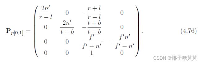
Some APIs (e.g., DirectX) map the near plane to z = 0 (instead of z = −1) and the far plane to z = 1. In addition, DirectX uses a left-handed coordinate system to define its projection matrix. This means DirectX looks along the positive z-axis and presents the near and far values as positive numbers. Here is the DirectX equation:
一些API(例如DirectX)将近平面映射到z = 0(而不是z = 1 ),将远平面映射到z = 1。此外,DirectX使用左手坐标系来定义其投影矩阵。这意味着DirectX沿着z轴的正方向看,并将远近值表示为正数。下面是DirectX等式:
One effect of using a perspective transformation is that the computed depth value does not vary linearly with the input pz value.
使用透视变换的一个效果是计算的深度值不会随着输入的pz值线性变化。
Using any of Equations 4.74–4.76 to multiply with a point p, we can see that
用方程4.74-4.76中的任何一个乘以点p,我们可以看到
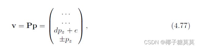
where the details of vx and vy have been omitted, and the constants d and f depend on the chosen matrix. If we use Equation 4.74, for example, then d = −(f′+n′)/(f′−n′),e = −2f′n′/(f′ − n′), and vx = −pz. To obtain the depth in normalized device coordinates (NDC), we need to divide by the w-component, which results in
其中省略了vx和vy的细节,常数d和f取决于所选的矩阵。例如,如果我们使用等式4.74,则d = −(f′+n′)/(f′−n′),e = −2f′n′/(f′ − n′),,vx = −pz.。要获得归一化设备坐标(NDC)中的深度,我们需要除以w分量,结果为

where zNDC ∈ [−1,+1] for the OpenGL projection. As can be seen, the output depth zNDC is inversely proportional to the input depth, pz.
其中,zNDC∈[-1,+1]用于OpenGL投影。可以看出,输出深度zNDC与输入深度pz成反比。
Figure 4.21 shows the effect of varying the distance of the near plane from the origin. Placement of the near and far planes affects the precision of the z-buffer. This effect is discussed further in Section 23.7.
图4.21显示了改变近平面到原点的距离的影响。近平面和远平面的放置会影响z缓冲区的精度。这种影响将在第23.7节中进一步讨论。
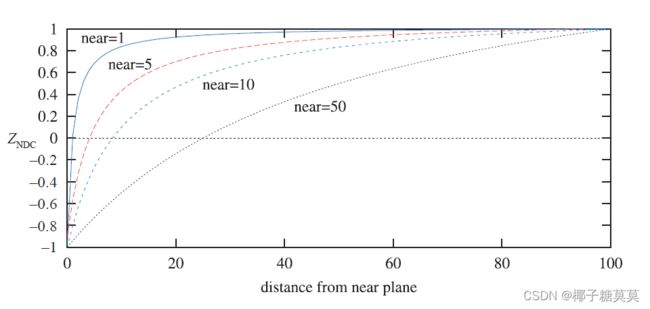
Figure 4.21. The effect of varying the distance of the near plane from the origin. The distance f′−n′ is kept constant at 100. As the near plane becomes closer to the origin, points nearer the far plane use a smaller range of the normalized device coordinate (NDC) depth space. This has the effect of making the z-buffer less accurate at greater distances.
图4.21。改变近平面到原点的距离的效果。距离f′-n′保持恒定为100。随着近平面越来越靠近原点,越靠近远平面的点使用的规格化设备坐标(NDC)深度空间的范围越来越小。这使得z缓冲器在更大的距离上不太精确。
There are several ways to increase the depth precision. A common method, which we call reversed z, is to store 1.0−zNDC either with floating point depth or with integers.
有几种方法可以提高深度精度。一种常见的方法是用浮点深度或整数来存储1.0-zNDC,我们称之为反转z。
A comparison is shown in Figure 4.22. Reed [1472] shows with simulations that using a floating point buffer with reversed z provides the best accuracy, and this is also the preferred method for integer depth buffers (which usually have 24 bits per depth).For the standard mapping (i.e., non-reversed z), separating the projection matrix in the transform decreases the error rate, as suggested by Upchurch and Desbrun.
比较如图4.22所示。Reed [1472]通过仿真表明,使用具有反转z的浮点缓冲器提供了最佳精度,并且这也是整数深度缓冲器(通常每个深度具有24位)的优选方法。对于标准映射(即,非反转z),在变换中分离投影矩阵降低了错误率,如Upchurch和Desbrun所建议的。
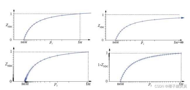
Figure 4.22. Different ways to set up the depth buffer with the DirectX transform, i.e., zNDC ∈ [0,+1].Top left: standard integer depth buffer, shown here with 4 bits of precision (hence the 16 marks on the y-axis). Top right: the far plane set to ∞, the small shifts on both axes showing that one does not lose much precision by doing so. Bottom left: with 3 exponent bits and 3 mantissa bits for floating point depth. Notice how the distribution is nonlinear on the y-axis, which makes it even worse on the x-axis. Bottom right: reversed floating point depth, i.e., 1 − zNDC, with a much better distribution as a result. (Illustrations courtesy of Nathan Reed.)
图4.22。使用DirectX变换设置深度缓冲器的不同方式,即zNDC ∈ [0,+1]。左上角:标准整数深度缓冲区,这里显示的精度为4位(因此y轴上有16个标记)。右上:远平面设置为∞,两个轴上的小位移表明这样做不会损失太多精度。左下角:浮点深度有3个指数位和3个尾数位。请注意,y轴上的分布是非线性的,这使得x轴上的分布更加糟糕。右下角:反向浮点深度,即1-zNDC,结果分布更好。(插图由内森·里德提供。)
For example, it can be better to use P(Mp) than Tp, where T = PM.Also, in the range of [0.5, 1.0], fp32 and int24 are quite similar in accuracy, since fp32 has a 23-bit mantissa. The reason for having zNDC proportional to 1/pz is that it makes hardware simpler and compression of depth more successful, which is discussed more in Section 23.7.
例如,使用P(Mp)可能比Tp更好,其中T = PM。此外,在[0.5,1.0]的范围内,fp32和int24在精度上非常相似,因为fp32具有23位尾数。使zNDC与1/pz成比例的原因是它使硬件更简单,深度压缩更成功,这将在23.7节中详细讨论。