python-opencv学习笔记(九):图像的仿射变换与应用实例
引言
本篇是在实验楼所做实验,因为感觉整个过程做得十分通畅,另外脉络比较清晰,加上了点自己的理解,整理成学习笔记。
图像平移
图像平移的数学推导
简单来说,图像的本质可以看做一个三维矩阵,第一维为长度,第二维是宽度,第三维是通道数(RGB),如果一张图在 python 中是一个变量 image,那么其长宽即 width, height = image.shape[:2]。
图像的平移就是在 xy 平面内对图像进行移动,所以该操作有两个自由度。其表达式为:
[ x ′ y ′ ] = [ 1 0 0 1 ] × [ x y ] + [ b 0 b 1 ] x ′ = x + b 0 y ′ = y + b 1 \begin{aligned} &{\left[\begin{array}{l} x^{\prime} \\ y^{\prime} \end{array}\right]=\left[\begin{array}{ll} 1 & 0 \\ 0 & 1 \end{array}\right] \times\left[\begin{array}{l} x \\ y \end{array}\right]+\left[\begin{array}{l} b_{0} \\ b_{1} \end{array}\right]} \\ &x^{\prime}=x+b_{0} \\ &y^{\prime}=y+b_{1} \end{aligned} [x′y′]=[1001]×[xy]+[b0b1]x′=x+b0y′=y+b1
其中, ( b 0 , b 1 ) (b_{0},b_{1}) (b0,b1)为偏移量, b 0 b_{0} b0为 x x x的偏移量, b 1 b_{1} b1是 y y y的偏移量,单位为像素。
例如,如果要将图像向右平移 10 个像素,向下平移 30 个像素,那么变换矩阵 M 表示为如下:
M = [ 1 0 10 0 1 30 ] M = \begin{bmatrix} 1& 0&10 \\ 0& 1&30 \end{bmatrix} M=[10011030]
代码实现
在opencv中,在平移之前,我们需要先构造一个移动矩阵,所谓移动矩阵,就是说明在 x 轴方向上移动多少距离,在 y 轴上移动多少距离。
可以通过 numpy 来构造这个矩阵,并将其传给仿射函数 cv2.warpAffine()。
仿射函数 cv2.warpAffine()传入三个参数:
- 图像变换的原始图像矩阵
- 移动矩阵
- 图像变换的大小
据此可以写一个demo,实现将图像向右平移 10 个像素,向下平移 30 个像素:
import cv2
import numpy as np

img = cv2.imread('lena.jpg')
height,width,channel = img.shape

# 声明变换矩阵 向右平移10个像素, 向下平移30个像素
M = np.float32([[1, 0, 10], [0, 1, 30]])
# 仿射变换
shifted = cv2.warpAffine(img, M, (width, height))

cv2.imwrite('shift_right_10_down_30.png', shifted)
如果要将图像向左平移 10 个像素, 向上平移 30 个像素,那么只需要将以上代码中声明变换矩阵的代码换为 M = np.float32([[1, 0, -10], [0, 1, -30]]),其它不变:
图像旋转
首先要明确旋转在二维中是绕着某一个点进行旋转,三维中是绕着某一个轴进行旋转。
图像旋转的数学推导
绕着坐标原点进行旋转
二维旋转中最简单的场景是绕着坐标原点进行的旋转,如下图所示:

如图所示点 v v v 绕原点旋转 θ θ θ 角,得到点 v ’ v’ v’,假设 v v v 点的坐标是 ( x , y ) (x, y) (x,y),那么可以推导得到 v ’ v’ v’ 点的坐标 ( x ’ , y ’ ) (x’, y’) (x’,y’)(设原点到 v v v 的距离是 r r r,原点到 v v v 点的向量与 x x x 轴的夹角是 ϕ ϕ ϕ )
x = r cos φ y = r sin φ x ′ = r cos ( θ + φ ) y ′ = r sin ( θ + φ ) \begin{gathered} x=r \cos \varphi \\ y=r \sin \varphi \\ x^{\prime}=r \cos (\theta+\varphi) \\ y^{\prime}=r \sin (\theta+\varphi) \end{gathered} x=rcosφy=rsinφx′=rcos(θ+φ)y′=rsin(θ+φ)
通过三角函数展开得到:
x ′ = r cos θ cos φ − r sin θ sin φ y ′ = r sin θ cos φ + r cos θ sin φ \begin{aligned} &x^{\prime}=r \cos \theta \cos \varphi-r \sin \theta \sin \varphi \\ &y^{\prime}=r \sin \theta \cos \varphi+r \cos \theta \sin \varphi \end{aligned} x′=rcosθcosφ−rsinθsinφy′=rsinθcosφ+rcosθsinφ
带入 x 和 y 表达式得到:
x ′ = x cos θ − y sin θ y ′ = x sin θ + y cos θ \begin{aligned} &x^{\prime}=x \cos \theta-y \sin \theta \\ &y^{\prime}=x \sin \theta+y \cos \theta \end{aligned} x′=xcosθ−ysinθy′=xsinθ+ycosθ
写成矩阵的形式是:
[ x ′ y ′ ] = [ cos θ − sin θ sin θ cos θ ] × [ x y ] + [ 0 0 ] M = [ cos θ − sin θ 0 sin θ cos θ 0 ] \begin{aligned} &{\left[\begin{array}{l} x^{\prime} \\ y^{\prime} \end{array}\right]=\left[\begin{array}{cc} \cos \theta & -\sin \theta \\ \sin \theta & \cos \theta \end{array}\right] \times\left[\begin{array}{l} x \\ y \end{array}\right]+\left[\begin{array}{l} 0 \\ 0 \end{array}\right]} \\ &M=\left[\begin{array}{ccc} \cos \theta & -\sin \theta & 0 \\ \sin \theta & \cos \theta & 0 \end{array}\right] \end{aligned} [x′y′]=[cosθsinθ−sinθcosθ]×[xy]+[00]M=[cosθsinθ−sinθcosθ00]
尽管图示中仅仅表示的是旋转一个锐角 θ 的情形,但是我们推导中使用的是三角函数的基本定义来计算坐标的,因此当旋转的角度是任意角度(例如大于 180 度,导致 v ’ v’ v’ 点进入到第四象限)结论仍然是成立的。
围绕任意点进行旋转
可以先把当前的旋转中心点平移到原点处, 在原点处旋转后再平移回去。
假定旋转中心为 ( c x , c y ) , M translation \left(c_{x}, c_{y}\right) , M_{\text {translation }} (cx,cy),Mtranslation 为平移矩阵, M translation − 1 M_{\text {translation }}{ }^{-1} Mtranslation −1 为平移矩阵的逆矩阵, M rotation M_{\text {rotation }} Mrotation 为原点旋转矩阵。
[ x ′ y ′ 0 ] = M − translation − 1 ( M − rotation ( M − translation [ x y 0 ] ) ) \left[\begin{array}{l} x^{\prime} \\ y^{\prime} \\ 0 \end{array}\right]=M_{-} \text {translation }{ }^{-1}\left(M_{-} \text {rotation }\left(M_{-} \operatorname{translation}\left[\begin{array}{l} x \\ y \\ 0 \end{array}\right]\right)\right) ⎣⎡x′y′0⎦⎤=M−translation −1⎝⎛M−rotation ⎝⎛M−translation⎣⎡xy0⎦⎤⎠⎞⎠⎞
其中:
M − translation = [ 1 0 − c x 0 1 − c y 0 0 1 ] M_{-} \text {translation }=\left[\begin{array}{ccc} 1 & 0 & -c_{x} \\ 0 & 1 & -c_{y} \\ 0 & 0 & 1 \end{array}\right] M−translation =⎣⎡100010−cx−cy1⎦⎤.而平移矩阵的逆矩阵为 M − translation − 1 = [ 1 0 c x 0 1 c y 0 0 1 ] M_{-} \text {translation }^{-1}=\left[\begin{array}{ccc} 1 & 0 & c_{x} \\ 0 & 1 & c_{y} \\ 0 & 0 & 1 \end{array}\right] M−translation −1=⎣⎡100010cxcy1⎦⎤,原点旋转矩阵为 M − rotation = [ cos θ − sin θ 0 sin θ cos θ 0 0 0 1 ] M_{-} \text {rotation }=\left[\begin{array}{ccc} \cos \theta & -\sin \theta & 0 \\ \sin \theta & \cos \theta & 0 \\ 0 & 0 & 1 \end{array}\right] M−rotation =⎣⎡cosθsinθ0−sinθcosθ0001⎦⎤
所以推出:
M = M − translation − 1 × M − rotation × M − translation = [ 1 0 c x 0 1 c y 0 0 1 ] × [ cos θ − sin θ 0 sin θ cos θ 0 0 0 1 ] × [ 1 0 − c x 0 1 − c y 0 0 1 ] = [ cos θ − sin θ ( 1 − cos θ ) ∗ c x + sin θ ∗ c y sin θ cos θ − sin θ ∗ c x + ( 1 − cos θ ) ∗ c y 0 0 1 ] \begin{aligned} M &=M_{-} \text {translation }{ }^{-1} \times M_{-} \text {rotation } \times M_{-} \text {translation } \\ &=\left[\begin{array}{ccc} 1 & 0 & c_{x} \\ 0 & 1 & c_{y} \\ 0 & 0 & 1 \end{array}\right] \times\left[\begin{array}{ccc} \cos \theta & -\sin \theta & 0 \\ \sin \theta & \cos \theta & 0 \\ 0 & 0 & 1 \end{array}\right] \times\left[\begin{array}{ccc} 1 & 0 & -c_{x} \\ 0 & 1 & -c_{y} \\ 0 & 0 & 1 \end{array}\right] \\ &=\left[\begin{array}{cccc} \cos \theta & -\sin \theta & (1-\cos \theta) * c_{x}+\sin \theta * c_{y} \\ \sin \theta & \cos \theta & -\sin \theta * c_{x}+(1-\cos \theta) * c_{y} \\ 0 & 0 & 1 \end{array}\right] \end{aligned} M=M−translation −1×M−rotation ×M−translation =⎣⎡100010cxcy1⎦⎤×⎣⎡cosθsinθ0−sinθcosθ0001⎦⎤×⎣⎡100010−cx−cy1⎦⎤=⎣⎡cosθsinθ0−sinθcosθ0(1−cosθ)∗cx+sinθ∗cy−sinθ∗cx+(1−cosθ)∗cy1⎦⎤
至此,为旋转的说明过程。
代码实现
绕着坐标原点进行旋转的方式在 OpenCV 中提供了 cv2.getRotationMatrix2D 函数获得变换矩阵。
- 第一参数指定旋转圆点;
- 第二个参数指定旋转角度;
- 第二个参数指定缩放比例。
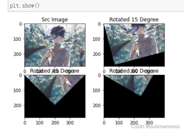
这里实现的效果为围绕原点将 lena 图像逆时针旋转 15/45/60 度:
import numpy as np
import cv2
import math
from matplotlib import pyplot as plt

img = cv2.imread('sub_picture.jpg')

height, width, channel = img.shape

def getRotationMatrix2D(theta):
    # 角度值转换为弧度值
    # 因为图像的左上角是原点 需要×-1
    theta = math.radians(-theta)

    M = np.float32([
        [math.cos(theta), -math.sin(theta), 0],
        [math.sin(theta), math.cos(theta), 0]])
    return M

# 进行仿射变换
# 围绕原点 逆时针旋转15度
M = getRotationMatrix2D(15)
rotated_15 = cv2.warpAffine(img, M, (width, height))

# 围绕原点 逆时针旋转45度
M = getRotationMatrix2D(45)
rotated_45 = cv2.warpAffine(img, M, (width, height))

# 围绕原点 逆时针旋转60度
M = getRotationMatrix2D(60)
rotated_60 = cv2.warpAffine(img, M, (width, height))

plt.subplot(221)
plt.title("Src Image")
plt.imshow(img[:,:,::-1])

plt.subplot(222)
plt.title("Rotated 15 Degree")
plt.imshow(rotated_15[:,:,::-1])

plt.subplot(223)
plt.title("Rotated 45 Degree")
plt.imshow(rotated_45[:,:,::-1])

plt.subplot(224)
plt.title("Rotated 60 Degree")
plt.imshow(rotated_60[:,:,::-1])

plt.show()
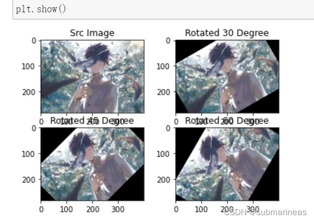
绕着坐标原点进行旋转的方式在 OpenCV 中将sub_picture 图像旋转 30/45/60 度代码为:
import numpy as np
import cv2
from math import cos,sin,radians
from matplotlib import pyplot as plt

img = cv2.imread('sub_picture.jpg')
height, width, channel = img.shape
theta = 45

def getRotationMatrix2D(theta, cx=0, cy=0):
    # 角度值转换为弧度值
    # 因为图像的左上角是原点 需要×-1
    theta = radians(-1 * theta)

    M = np.float32([
        [cos(theta), -sin(theta), (1-cos(theta))*cx + sin(theta)*cy],
        [sin(theta), cos(theta), -sin(theta)*cx + (1-cos(theta))*cy]])
    return M

# 求得图片中心点, 作为旋转的轴心
cx = int(width / 2)
cy = int(height / 2)

# 进行仿射变换
# 围绕原点 逆时针旋转30度
M = getRotationMatrix2D(30, cx=cx, cy=cy)
rotated_30 = cv2.warpAffine(img, M, (width, height))

# 围绕原点 逆时针旋转45度
M = getRotationMatrix2D(45, cx=cx, cy=cy)
rotated_45 = cv2.warpAffine(img, M, (width, height))

# 围绕原点 逆时针旋转60度
M = getRotationMatrix2D(60, cx=cx, cy=cy)
rotated_60 = cv2.warpAffine(img, M, (width, height))

plt.subplot(221)
plt.title("Src Image")
plt.imshow(img[:,:,::-1])

plt.subplot(222)
plt.title("Rotated 30 Degree")
plt.imshow(rotated_30[:,:,::-1])

plt.subplot(223)
plt.title("Rotated 45 Degree")
plt.imshow(rotated_45[:,:,::-1])

plt.subplot(224)
plt.title("Rotated 60 Degree")
plt.imshow(rotated_60[:,:,::-1])

plt.show()
图像缩放
图像缩放的数学推导
对图像的伸缩变换的变换矩阵 M 为:
[ x ′ y ′ ] = [ f x 0 0 f y ] × [ x y ] + [ 0 0 ] \left[\begin{array}{l} x^{\prime} \\ y^{\prime} \end{array}\right]=\left[\begin{array}{cc} f_{x} & 0 \\ 0 & f_{y} \end{array}\right] \times\left[\begin{array}{l} x \\ y \end{array}\right]+\left[\begin{array}{l} 0 \\ 0 \end{array}\right] [x′y′]=[fx00fy]×[xy]+[00]
其中, f x f_{x} fx代表 x x x轴的焦距(缩放因子), f y f_{y} fy代表 y y y轴的焦距(缩放因子).
化简可以分别得到 x ′ x^{\prime} x′ 和 y ′ y^{\prime} y′:
x ′ = f x ∗ x y ′ = f y ∗ y \begin{aligned} &x^{\prime}=f_{x} * x \\ &y^{\prime}=f_{y} * y \end{aligned} x′=fx∗xy′=fy∗y
代码实现
图像的放大和缩小有一个专门的函数:cv2.resize(),这其中就需要设置缩放的比例,一种办法是设置缩放因子,另一种办法是直接设置图像的大小。resize 函数可表示为:
resize(src, dsize[, dst[, fx[, fy[, interpolation]]]]) -> dst
函数对应的参数解析:
src输入图片dsize输出图片的尺寸dst输出图片fxx 轴的缩放因子fyy 轴的缩放因子interpolation插值方式INTER_NEAREST- 最近邻插值INTER_LINEAR- 线性插值(默认)INTER_AREA- 区域插值INTER_CUBIC- 三次样条插值INTER_LANCZOS4- Lanczos 插值
在缩放以后,图像必然会发生变化,这就涉及到图像的插值问题。缩放有几种不同的插值(interpolation)方法,在缩小时推荐使用cv2.INTER_AREA,扩大时推荐使用 cv2.INTER_CUBIC 和cv2.INTER_LINEAR。
如下例子通过两种方式实现对 sub_picture 图片的缩放:
图像翻转
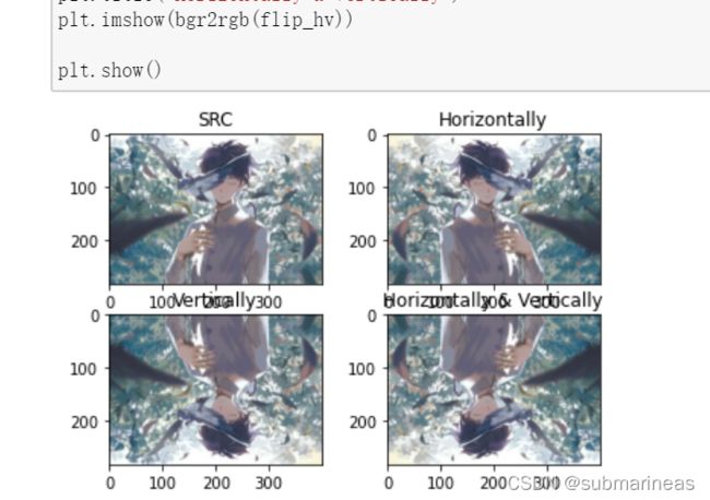
图像翻转可以分为水平翻转、垂直翻转以及同时水平翻转和垂直翻转,具体公式遇到可分为如下:(注: width 代表图像的宽度 height 代表图像的高度)
图像翻转推导
水平翻转的变换矩阵:
[ x ′ y ′ ] = [ − 1 0 0 1 ] × [ x y ] + [ width 0 ] M = [ − 1 0 width 0 1 0 ] \begin{aligned} &{\left[\begin{array}{l} x^{\prime} \\ y^{\prime} \end{array}\right]=\left[\begin{array}{cc} -1 & 0 \\ 0 & 1 \end{array}\right] \times\left[\begin{array}{l} x \\ y \end{array}\right]+\left[\begin{array}{c} \text { width } \\ 0 \end{array}\right]} \\ &M=\left[\begin{array}{ccc} -1 & 0 & \text { width } \\ 0 & 1 & 0 \end{array}\right] \end{aligned} [x′y′]=[−1001]×[xy]+[ width 0]M=[−1001 width 0]
垂直翻转的变换矩阵:
[ x ′ y ′ ] = [ 1 0 0 − 1 ] × [ x y ] + [ 0 height ] M = [ 1 0 0 0 − 1 height ] \begin{aligned} &{\left[\begin{array}{l} x^{\prime} \\ y^{\prime} \end{array}\right]=\left[\begin{array}{cc} 1 & 0 \\ 0 & -1 \end{array}\right] \times\left[\begin{array}{l} x \\ y \end{array}\right]+\left[\begin{array}{c} 0 \\ \text { height } \end{array}\right]} \\ &M=\left[\begin{array}{ccc} 1 & 0 & 0 \\ 0 & -1 & \text { height } \end{array}\right] \end{aligned} [x′y′]=[100−1]×[xy]+[0 height ]M=[100−10 height ]
同时进行水平翻转与垂直翻转:
[ x ′ y ′ ] = [ 1 0 0 − 1 ] × [ x y ] + [ w i d t h height ] M = [ 1 0 w i d t h 0 − 1 height ] \begin{aligned} &{\left[\begin{array}{l} x^{\prime} \\ y^{\prime} \end{array}\right]=\left[\begin{array}{cc} 1 & 0 \\ 0 & -1 \end{array}\right] \times\left[\begin{array}{l} x \\ y \end{array}\right]+\left[\begin{array}{c} width \\ \text { height } \end{array}\right]} \\ &M=\left[\begin{array}{ccc} 1 & 0 & width \\ 0 & -1 & \text { height } \end{array}\right] \end{aligned} [x′y′]=[100−1]×[xy]+[width height ]M=[100−1width height ]
代码实现
import cv2
import numpy as np
from matplotlib import pyplot as plt

img = cv2.imread('sub_picture.jpg')
height,width,channel = img.shape

# 水平翻转
M1 = np.float32([[-1, 0, width], [0, 1, 0]])
flip_h =  cv2.warpAffine(img, M1, (width, height))

# 垂直翻转
M2 = np.float32([[1, 0, 0], [0, -1, height]])
flip_v =  cv2.warpAffine(img, M2, (width, height))

# 水平垂直同时翻转
M3 = np.float32([[-1, 0, width], [0, -1, height]])
flip_hv =  cv2.warpAffine(img, M3, (width, height))

# 将颜色空间从BGR转换为RGB
def bgr2rgb(img):
    return img[:,:,::-1]

plt.subplot(221)
plt.title('SRC')
plt.imshow(bgr2rgb(img))

plt.subplot(222)
plt.title('Horizontally')
plt.imshow(bgr2rgb(flip_h))

plt.subplot(223)
plt.title('Vertically')
plt.imshow(bgr2rgb(flip_v))

plt.subplot(224)
plt.title('Horizontally & Vertically')
plt.imshow(bgr2rgb(flip_hv))

plt.show()
实例:提取手写数字图片样本
我们需要先制作一张写有 1-9 之间数字的图片:
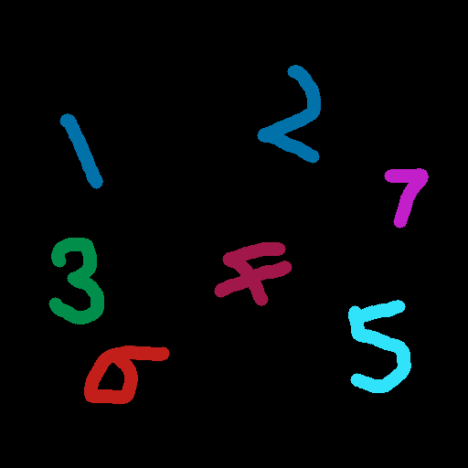
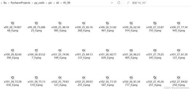
这个我本来想用代码来做,但这种必须有模板,特别是这种在空间中数字旋转角度与字体都有所改变的,网上的方法大多基于 MNIST 数据集,我试了脚本之家下Python生成数字图片代码分享的其中旋转生成字体的demo,其中有两个bug顺带修改了:
# -*- coding:utf-8 -*-
from PIL import Image,ImageFont,ImageDraw,ImageFilter
import random
import os
import time
class Captcha(object):
  def __init__(self,size=(20,24),fontSize=20):
    self.font = ImageFont.truetype('Arial.ttf',fontSize)
    self.size = size
    self.image = Image.new('RGBA',self.size,(255,)*4)
    self.text = ''
  def rotate(self, angle):
    rot = self.image.rotate(angle,expand=0)
    fff = Image.new('RGBA',rot.size,(255,)*4)
    self.image = Image.composite(rot,fff,rot)
  def randColor(self):
    self.fontColor = (random.randint(0,250),random.randint(0,250),random.randint(0,250))

  def setNum(self, num):
    return num;
  def write(self,text,x,y):
    draw = ImageDraw.Draw(self.image)
    draw.text((x,y),text,fill=self.fontColor,font=self.font)
  def writeNum(self, num, angle):
    x = 2
    y = -2
    self.text = num
    self.fontColor = (0, 0, 0)
    self.write(num, x, y)
    self.rotate(angle)
    return self.text
  def save(self, save_path):
    # self.image = self.image.filter(ImageFilter.EDGE_ENHANCE_MORE) #滤镜,边界加强
    self.image.save(save_path)
pic_root_path = './pic'
if not os.path.exists(pic_root_path):
  os.mkdir(pic_root_path)
angles = [(45,90),(-45,45),(-90,-45)]
for i in range(10):
  pic_num_path = os.path.join(pic_root_path, 'x'+str(i))
  if not os.path.exists(pic_num_path):
    os.mkdir(pic_num_path)
  for angle_i in angles:
    angle_name = str(angle_i[0])+'_'+str(angle_i[1])
    pic_angle_path = os.path.join(pic_num_path, angle_name)
    if not os.path.exists(pic_angle_path):
      os.mkdir(pic_angle_path)
    for fontsize in range(25,29):
      for j in range(2500):
        # Keep 5 decimal places
        angle = round(random.uniform(angle_i[0], angle_i[1]),5)
        img = Captcha(size=(20, 24), fontSize=fontsize)
        num = img.writeNum(str(i), angle)
        img_name = 'x'+str(j)+'_'+str(fontsize)+'_'+str(angle)+'_'+str(num)+'.png'
        print(img_name,".....img_name....")
        save_path = os.path.join(pic_angle_path, img_name)
        print(save_path,"........save_path......")
        # print(dir(Captcha))
        # img=img.convert('RGB')
        img.save(save_path)
另外就是记起来之前有写过一篇Django的web验证码登录注册功能,有做的验证码图片,但那是一个维度,而且有模板模块,如果要将其扩展,好像也很难,翻了下之前做的图为:
![]()
那这里就用上面那张图做如下实验,我们可以根据 minAreaRect 函数返回的数据结构,用来提取最小外接矩形区域, 以矩形中心 (cx, cy) 作为对原来图像旋转的中心点,旋转角度设定为 theta:
# 声明旋转矩阵
rotateMatrix = cv2.getRotationMatrix2D((cx, cy), theta, 1.0)
# 获取旋转后的图像
rotatedImg = cv2.warpAffine(img, rotateMatrix, (img.shape[1], img.shape[0]))
运行代码为:
'''
    利用minAreaRect绘制最小面积矩形并绘制
'''
import numpy as np
import cv2

# 读入黑背景下的彩色手写数字
img = cv2.imread("random_color_number.jpg")
# 转换为gray灰度图
gray = cv2.cvtColor(img, cv2.COLOR_BGR2GRAY)
# 寻找轮廓
contours, hier = cv2.findContours(gray, cv2.RETR_EXTERNAL, cv2.CHAIN_APPROX_SIMPLE)

for cidx,cnt in enumerate(contours):
    minAreaRect = cv2.minAreaRect(cnt)
    # 转换为整数点集坐标
    # rectCnt = np.int64(cv2.boxPoints(minAreaRect))
    ((cx, cy), (w, h), theta) = minAreaRect

    cx = int(cx)
    cy = int(cy)
    w = int(w)
    h = int(h)
    # 获取旋转矩阵
    rotateMatrix = cv2.getRotationMatrix2D((cx, cy), theta, 1.0)
    rotatedImg = cv2.warpAffine(img, rotateMatrix, (img.shape[1], img.shape[0]))
    pt1 = (int(cx - w/2), int(cy - h/2))
    pt2 = (int(cx + w/2), int(cy + h/2))
    # 原图绘制矩形区域
    cv2.rectangle(rotatedImg, pt1=pt1, pt2=pt2,color=(255, 255, 255), thickness=3)
    # 绘制中心点
    cv2.circle(rotatedImg, (cx, cy), 5, color=(255, 0, 0), thickness=-1)
    cv2.imwrite("minarearect_cidx_{}.png".format(cidx), rotatedImg)
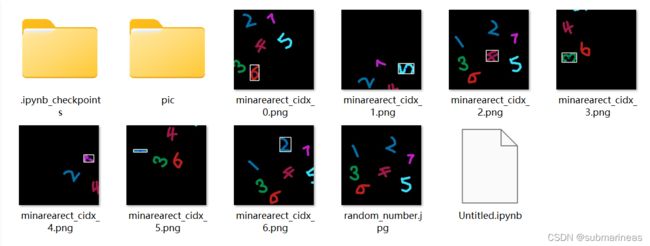
在对手写数字图片样本进行提取之前需要先将图片转为灰度图,再进行轮廓提取。需要用到的函数为 boudningRect(),用来获取正外接矩形,传入的参数为轮廓点集(单个) Points。具体用法如下:
rect = cv2.boundingRect(cnt)
(x, y, w, h) = rect
完整代码为:
import numpy as np
import cv2

# 读入黑背景下的彩色手写数字
img = cv2.imread("random_color_number.jpg")
# 转换为gray灰度图
gray = cv2.cvtColor(img, cv2.COLOR_BGR2GRAY)
# 寻找轮廓
contours, hier = cv2.findContours(gray, cv2.RETR_EXTERNAL, cv2.CHAIN_APPROX_SIMPLE)

# 声明画布 拷贝自img
canvas = np.copy(img)

for cidx,cnt in enumerate(contours):
    (x, y, w, h) = cv2.boundingRect(cnt)
    print('RECT: x={}, y={}, w={}, h={}'.format(x, y, w, h))
    # 原图绘制圆形
    cv2.rectangle(canvas, pt1=(x, y), pt2=(x+w, y+h),color=(255, 255, 255), thickness=3)
    # 截取ROI图像
    cv2.imwrite("number_boudingrect_cidx_{}.png".format(cidx), img[y:y+h, x:x+w])

cv2.imwrite("number_boundingrect_canvas.png", canvas)
"""
RECT: x=92, y=378, w=94, h=64
RECT: x=381, y=328, w=69, h=102
RECT: x=234, y=265, w=86, h=70
RECT: x=53, y=260, w=61, h=95
RECT: x=420, y=184, w=49, h=66
RECT: x=65, y=124, w=48, h=83
RECT: x=281, y=71, w=70, h=108
True
"""

