移位寄存器——用Verilog实现串入串出、串并和并串转换并进行Modelsim仿真
文章目录
-
- 用Verilog实现串并和并串转换
- 一、了解并串和串并转换的原理
-
- 并串转换
- 串并转换
- 转换可以采用两种方式实现
- 二、串转并(以一输入八输出为例)
-
- 2.1 Verilog实现左移和右移
- 2.2 msb最高位优先(利用计数器实现串转并)
- 2.3 LSB最低位优先
- 三、并转串(以八输入一输出为例)
-
- 采用计数器的方式实现移位
- 运算符实现移位
- 串入串出移位寄存器
用Verilog实现串并和并串转换
一、了解并串和串并转换的原理
串行数据输出是将组成数据和字符的码元按时序逐位予以传输,并行数据传输是将固定位数(通常为8位或16位等)的数据和字符码元同时传输至接收端,串并转换是完成这两种传输方式之间转换的技术。
例如:需要传输的数据有32bit,用串行传输则需要32个时钟周期完成传输,如果用8位并行传输,则32bit数据只需要4个时钟周期就可以完成传输。
并串转换
并转串电路主要由时钟(clk)、复位信号(rst)、并行输入信号(pdin)、串行输出信号(sdout)和使能信号(en)组成。使能信号表示开始执行并转串操作,由于并转串是移位操作,先将八位数据暂存于一个八位寄存器器中,然后左移输出到一位输出端口,通过一个“移位”来实现,当一次并转串完成后,需要重新载入待转换的并行数据时,使能信号要再起来一次。
串并转换
输入一位的数据,每一个clk接收一位,最终以多位(8位)的形式输出。通常采用位拼接的方式来实现。典型的案例,给一位输入,实现8位数据的左移和右移操作。
右移:舍弃低位,高位补输入的值
左移:舍弃高位,低位补输入的值。
转换可以采用两种方式实现
一:lsb优先 Least Significant Bit,最低比特,最低位优先
二:msb优先 Most Significant Bit,最高比特,最高位优先
二、串转并(以一输入八输出为例)
2.1 Verilog实现左移和右移
通过位拼接运算符来进行高位舍去,实现左移
module Deserialize(
    input           clk,
    input           rst_n,
    input         data_i,
    output   reg [7:0] data_o
    );

//lsb first

always @(posedge clk or negedge rst_n)begin
    if(rst_n == 1'b0)begin
        data_o <= 8'b0;
    end
    else begin
        data_o <= {data_o[6:0], data_i}; //去掉了高位,让data_i来代替高位,相当于左移一位
    end
end
endmodule
补充: 截取数据的不同位数进行拼接:
 例:    data1 = 0101_1101
         data2 = 1011_0011
         data = {data1[3:0],data2[7:4]}
        则可得:data = 1101_1011
testbench仿真
`timescale 1ns/1ns
`define clock_period 20

module Deserialize_tb;
   reg clk;
	reg rst_n;
	reg data_i;

wire [7:0] data_o;


Deserialize  Deserialize_0(
  .clk(clk),
  .rst_n(rst_n),
  .data_i(data_i),
  .data_o(data_o)
  );

  initial clk = 1;

  always #(`clock_period/2) clk = ~clk;


  initial begin
	   rst_n=0;
		data_i=0;

 #(`clock_period*200)
   rst_n=1;
 #(`clock_period*200)
  data_i=1;
   #(`clock_period*200)
  $stop;
  end

  endmodule
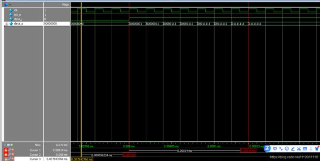
波形图如下,可看到输入为0的时候,输出一直是00000000,当输入为高电平,即可用输入的1来补低位,从而高位被舍弃,也就实现了左移的操作。

分析:每当clk上升沿且rst_n=1时变化,开始时data_i=0,此时data_o=0000_0000,当data_i=1时,则 data_o <= {data_o[6:0], data_i};data_o=0000_0001,实现了高位舍弃,低位用data_i作为新输入的数据来成为data_o的最低位。
至此,我们可以继续尝试右移的写法。
核心代码如下:
data_o <= {data_in,data_o[7:1]}; //右移
2.2 msb最高位优先(利用计数器实现串转并)
代码:
module invert(input  in,input clk,input rst_n, output reg  [2:0] cnt,output reg [7:0] out);

	always@(posedge clk)
        if(!rst_n)begin
            out <= 8'd0;
            cnt <= 3'd0;
    end
        else if(cnt == 3'd7)
           cnt <= 3'd0;
       else begin
            cnt <= cnt + 1'd1;
           out[7-cnt] <= in; //输入补最高位,实现右移.//用计数来进行7-0的移位操作
       end
       endmodule
tb文件:
`timescale 1ps/1ps
	module nvert_tb ();
	reg clk=0;
    reg rst_n;
    wire  [2:0] cnt;
    wire [7:0]out;
	always #5 clk = ~clk;  // Create clock with period=10

    reg   in;
	initial begin
        rst_n = 0;
        in = 1;
        #10;
        rst_n = 1;
        #6;
        in = 1;
        #80;
        in = 0;
		$display ("The current time is (%0d ps)", $time);
		#100 $finish;            // Quit the simulation
	end

    invert inst1 ( .in(in) ,.clk(clk),.rst_n(rst_n),.cnt(cnt),.out(out) );   // Sub-modules work too.

endmodule
波形图
可看到,输入in = 1,在clk上升沿,接收输入in的值,补高位,从而实现了右移。

2.3 LSB最低位优先
至此,我们可以继续尝试LSB最低位优先的写法。
核心代码如下:
out[cnt] <= in; //输入补最高位,实现左移
三、并转串(以八输入一输出为例)
采用计数器的方式实现移位
cnt : 0-7 的计数,因此将in从低位开始输出。
module invert(input [7:0] in,input clk,input rst_n, output reg  [2:0] cnt,output reg  out);

	always@(posedge clk)
        if(!rst_n)begin
            out <= 3'd0;
            cnt <= 3'd0;
    end
        else if(cnt == 3'd7)
           cnt <= 3'd0;
       else begin
            cnt <= cnt + 1'd1;
           out <= in[cnt];
    end
endmodule
如下可以看到,给八位输入,最终得到一位输出。
同时,当cnt=0的时候,在下一clk上升沿,输出00000001最低位为1,cnt=1,输出00000111 中的in[1]为1,cnt = 2 ,输出1;cnt = 3 输出in[3]为0,以此类推。

运算符实现移位
module invert(input [7:0]  in,input clk,input rst_n,input en,output   out);
    reg  [7:0] shift_out;

	always@(posedge clk)
        if(!rst_n)
            shift_out <= 0;
        else if(en == 1)
           shift_out <= in;
        else
        shift_out <= shift_out <<1;
    assign out = shift_out[7];
tb文件:
`timecasle 1ps/1ps
module top_module ();
	reg clk=0;
    reg rst_n;
    reg en;
    wire out;
	always #5 clk = ~clk;  // Create clock with period=10

    reg   [7:0] in;
	initial begin
        rst_n = 0;
        in = 1;
        en = 0;
        #10;
        rst_n = 1;
        #10;
        en = 1; //可以将in给shifout暂存
        #10
        en = 0; //开始移位
        #80;
        en = 1;
        in = 8'b00000111;
        #10;
        en = 0;
        #10;
        en = 0;
        #80;
        in = 0;
		$display ("The current time is (%0d ps)", $time);
		#120 $finish;            // Quit the simulation
	end

    invert inst1 ( .in(in) ,.clk(clk),.rst_n(rst_n),.en(en),.out(out) );   // Sub-modules work too.

endmodule
串入串出移位寄存器
如下是8个D触发器构成的八位移位寄存器。数据在时钟下一位一位的传输,实现数据的先入先出。

这里直接采用在线的HDLBits仿真器进行仿真。代码如下:
module top_module ();
	reg clk=0;
	always #5 clk = ~clk;  // Create clock with period=10
	initial `probe_start;   // Start the timing diagram

	`probe(clk);        // Probe signal "clk"

	reg in=0;
    wire out;
	initial begin
		#10 in = 1;
		#10 in = 0;
		#20 in = 1;
		#20 in = 0;
		$display ("Hello world! The current time is (%0d ps)", $time);
		#100 $finish;            // Quit the simulation
	end

	   invert inst1 ( .in(in) ,.clk(clk),.out(out) );    // Sub-modules work too.

endmodule

module invert(input in,input clk,output reg out );
	reg tmp1,tmp2,tmp3,tmp4,tmp5,tmp6,tmp7;

	always@(posedge clk)
      	begin
		tmp1<=in;
		tmp2<=tmp1;
		tmp3<=tmp2;
		tmp4<=tmp3;
		tmp5<=tmp4;
		tmp6<=tmp5;
		tmp7<=tmp6;
		out<=tmp7;
        end
        `probe(in);	// Sub-modules can also have `probe()
        `probe(out);
endmodule


