【STM32】端口GPIO详解
前注:本文章主要讲解【原理】【固件库(标准库)】【HAL库】
内容为 '_Snake_'编写,日常学习总结,内容如有不足、不妥之处请私信告知,谢谢!
实验:
实验配置
A.硬件原理
一、GPIO通用
1.GPIO简介
2.GPIO主要特性
- 输出状态:推挽或开漏 + 上拉/下拉
- 从输出数据寄存器 (GPIOx_ODR) 或外设(复用功能输出)输出数据
- 可为每个 I/O 选择不同的速度
- 输入状态:浮空、上拉/下拉、模拟
- 将数据输入到输入数据寄存器 (GPIOx_IDR) 或外设(复用功能输入)
- 置位和复位寄存器 (GPIOx_BSRR),对 GPIOx_ODR 具有按位写权限
- 锁定机制 (GPIOx_LCKR),可冻结 I/O 配置
- 模拟功能
- 复用功能输入/输出选择寄存器(一个 I/O 最多可具有 16 个复用功能)
- 快速翻转,每次翻转最快只需要两个时钟周期
- 引脚复用非常灵活,允许将 I/O 引脚用作 GPIO 或多种外设功能中的一种
3.GPIO功能描述
- ─ 输入浮空
- ─ 输入上拉
- ─ 输入下拉
- ─ 模拟输入
- ─ 开漏输出
- ─ 推挽式输出
- ─ 推挽式复用功能
- ─ 开漏复用功能
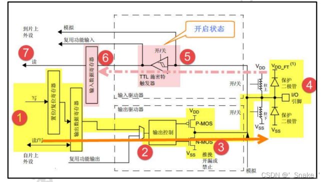
I/O端口位的基本结构
5伏兼容I/O端口位的基本结构
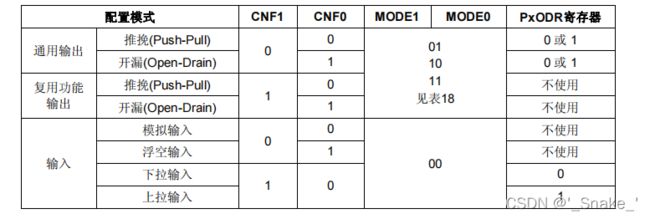
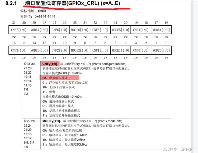
端口位配置表
输出模式位
输入配置
- 输出缓冲器被禁止
- 施密特触发输入被激活
- 根据输入配置(上拉,下拉或浮动)的不同,弱上拉和下拉电阻被连接
- 出现在I/O脚上的数据在每个APB2时钟被采样到输入数据寄存器
- 对输入数据寄存器的读访问可得到I/O状态
输出配置
- 输出缓冲器被激活 ─ 开漏模式:输出寄存器上的’0’激活N-MOS,而输出寄存器上的’1’将端口置于高阻状态(P-MOS从不被激活)。 ─ 推挽模式:输出寄存器上的’0’激活N-MOS,而输出寄存器上的’1’将激活P-MOS。
- 施密特触发输入被激活
- 弱上拉和下拉电阻被禁止
- 出现在I/O脚上的数据在每个APB2时钟被采样到输入数据寄存器
- 在开漏模式时,对输入数据寄存器的读访问可得到I/O状态
- 在推挽式模式时,对输出数据寄存器的读访问得到最后一次写的值。
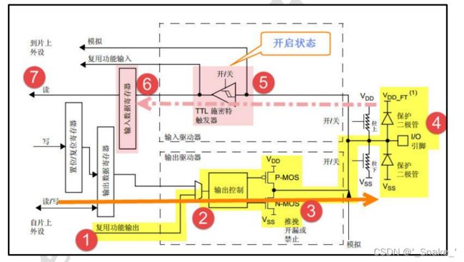
复用功能配置
- 在开漏或推挽式配置中,输出缓冲器被打开
- 内置外设的信号驱动输出缓冲器(复用功能输出)
- 施密特触发输入被激活
- 弱上拉和下拉电阻被禁止
- 在每个APB2时钟周期,出现在I/O脚上的数据被采样到输入数据寄存器
- 开漏模式时,读输入数据寄存器时可得到I/O口状态
- 在推挽模式时,读输出数据寄存器时可得到最后一次写的值
模拟输入配置
- 输出缓冲器被禁止;
- 禁止施密特触发输入,实现了每个模拟I/O引脚上的零消耗。施密特触发输出值被强置
- 为’0’;
- 弱上拉和下拉电阻被禁止;
- 读取输入数据寄存器时数值为’0’。
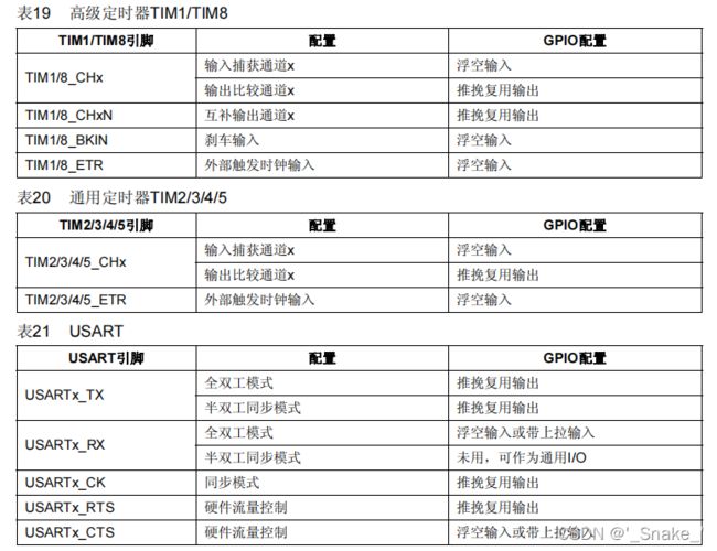
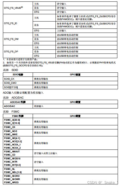
外设的GPIO配置
模式配置
输入:
1.输入浮空
2. 输入上拉模式
3. 输入下拉模式
输出:
5. 开漏通用输出模式

6. 推挽通用输出模式
7. 推挽复用功能输出模式
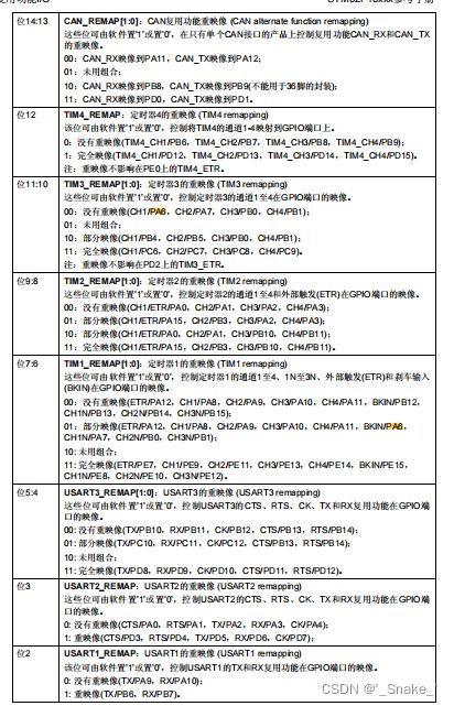
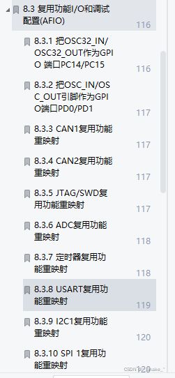
二、复用引脚
需要用到外设的重映射功能需要开启。
部分重映射,完全重映射
B.固件库
涉及文件stm32f10x_gpio.h、stm32f10x_gpio.c、stm32f10x.h
寄存器结构体与地址(stm32f10x.h)
typedef struct
{
  __IO uint32_t CRL;    //端口配置低寄存器(GPIOx_CRL)
  __IO uint32_t CRH;    //端口配置高寄存器(GPIOx_CRH)
  __IO uint32_t IDR;    //端口输入数据寄存器(GPIOx_IDR)
  __IO uint32_t ODR;    //端口输出数据寄存器(GPIOx_ODR)
  __IO uint32_t BSRR;   //端口位设置/清除寄存器(GPIOx_BSRR)
  __IO uint32_t BRR;    //端口位清除寄存器(GPIOx_BRR)
  __IO uint32_t LCKR;   //端口配置锁定寄存器(GPIOx_LCKR)
} GPIO_TypeDef;
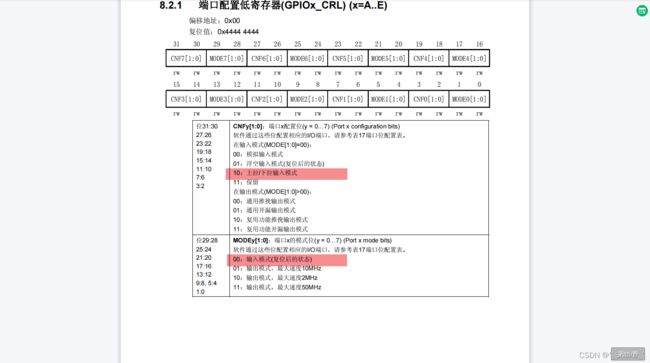
具体寄存器详情看手册
#define PERIPH_BASE           ((uint32_t)0x40000000)        //外设基地址

#define APB2PERIPH_BASE       (PERIPH_BASE + 0x10000)       //APB2基地址


/*GPIO的基地址*/
#define GPIOA_BASE            (APB2PERIPH_BASE + 0x0800)
#define GPIOB_BASE            (APB2PERIPH_BASE + 0x0C00)
#define GPIOC_BASE            (APB2PERIPH_BASE + 0x1000)
#define GPIOD_BASE            (APB2PERIPH_BASE + 0x1400)
#define GPIOE_BASE            (APB2PERIPH_BASE + 0x1800)
#define GPIOF_BASE            (APB2PERIPH_BASE + 0x1C00)
#define GPIOG_BASE            (APB2PERIPH_BASE + 0x2000)

/*函数调用时用的端口*/
#define GPIOA               ((GPIO_TypeDef *) GPIOA_BASE)
#define GPIOB               ((GPIO_TypeDef *) GPIOB_BASE)
#define GPIOC               ((GPIO_TypeDef *) GPIOC_BASE)
#define GPIOD               ((GPIO_TypeDef *) GPIOD_BASE)
#define GPIOE               ((GPIO_TypeDef *) GPIOE_BASE)
#define GPIOF               ((GPIO_TypeDef *) GPIOF_BASE)
#define GPIOG               ((GPIO_TypeDef *) GPIOG_BASE)
                                ↑
                                ↑
                                ↑
                        GPIO寄存器的结构体
函数结构体(stm32f10x_gpio.h)
GPIO初始化结构体
typedef struct
{
  uint16_t GPIO_Pin;                 //引脚号 例如GPIO_Pin_0

  GPIOSpeed_TypeDef GPIO_Speed;      //I/O口驱动电路的响应速度

  GPIOMode_TypeDef GPIO_Mode;        //GPIO 工作模式
}GPIO_InitTypeDef;
引脚号(看芯片型号)
#define GPIO_Pin_0                 ((uint16_t)0x0001)  /*!< Pin 0 selected */
#define GPIO_Pin_1                 ((uint16_t)0x0002)  /*!< Pin 1 selected */
#define GPIO_Pin_2                 ((uint16_t)0x0004)  /*!< Pin 2 selected */
#define GPIO_Pin_3                 ((uint16_t)0x0008)  /*!< Pin 3 selected */
#define GPIO_Pin_4                 ((uint16_t)0x0010)  /*!< Pin 4 selected */
#define GPIO_Pin_5                 ((uint16_t)0x0020)  /*!< Pin 5 selected */
#define GPIO_Pin_6                 ((uint16_t)0x0040)  /*!< Pin 6 selected */
#define GPIO_Pin_7                 ((uint16_t)0x0080)  /*!< Pin 7 selected */
#define GPIO_Pin_8                 ((uint16_t)0x0100)  /*!< Pin 8 selected */
#define GPIO_Pin_9                 ((uint16_t)0x0200)  /*!< Pin 9 selected */
#define GPIO_Pin_10                ((uint16_t)0x0400)  /*!< Pin 10 selected */
#define GPIO_Pin_11                ((uint16_t)0x0800)  /*!< Pin 11 selected */
#define GPIO_Pin_12                ((uint16_t)0x1000)  /*!< Pin 12 selected */
#define GPIO_Pin_13                ((uint16_t)0x2000)  /*!< Pin 13 selected */
#define GPIO_Pin_14                ((uint16_t)0x4000)  /*!< Pin 14 selected */
#define GPIO_Pin_15                ((uint16_t)0x8000)  /*!< Pin 15 selected */
#define GPIO_Pin_All               ((uint16_t)0xFFFF)  /*!< All pins selected */
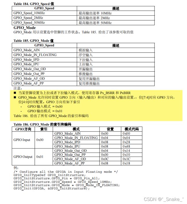
GPIO 工作模式
typedef enum
{ GPIO_Mode_AIN = 0x0,         //模拟输入
 GPIO_Mode_IN_FLOATING = 0x04, //浮空输入
 GPIO_Mode_IPD = 0x28,         //下拉输入
 GPIO_Mode_IPU = 0x48,         //上拉输入
 GPIO_Mode_Out_OD = 0x14,      //开漏输出
 GPIO_Mode_Out_PP = 0x10,      //通用推挽输出
 GPIO_Mode_AF_OD = 0x1C,       //复用开漏输出
 GPIO_Mode_AF_PP = 0x18        //复用推挽
}GPIOMode_TypeDef;
IO 口速度设置
typedef enum
{
 GPIO_Speed_10MHz = 1,
 GPIO_Speed_2MHz,
 GPIO_Speed_50MHz
}GPIOSpeed_TypeDef;
函数(stm32f10x_gpio.c)
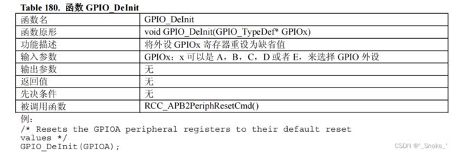
GPIO_DeInit
void GPIO_DeInit(GPIO_TypeDef* GPIOx)
{
  /* Check the parameters */
  assert_param(IS_GPIO_ALL_PERIPH(GPIOx));

  if (GPIOx == GPIOA)
  {
    RCC_APB2PeriphResetCmd(RCC_APB2Periph_GPIOA, ENABLE);
    RCC_APB2PeriphResetCmd(RCC_APB2Periph_GPIOA, DISABLE);
  }
  else if (GPIOx == GPIOB)
  {
    RCC_APB2PeriphResetCmd(RCC_APB2Periph_GPIOB, ENABLE);
    RCC_APB2PeriphResetCmd(RCC_APB2Periph_GPIOB, DISABLE);
  }
  else if (GPIOx == GPIOC)
  {
    RCC_APB2PeriphResetCmd(RCC_APB2Periph_GPIOC, ENABLE);
    RCC_APB2PeriphResetCmd(RCC_APB2Periph_GPIOC, DISABLE);
  }
  else if (GPIOx == GPIOD)
  {
    RCC_APB2PeriphResetCmd(RCC_APB2Periph_GPIOD, ENABLE);
    RCC_APB2PeriphResetCmd(RCC_APB2Periph_GPIOD, DISABLE);
  }
  else if (GPIOx == GPIOE)
  {
    RCC_APB2PeriphResetCmd(RCC_APB2Periph_GPIOE, ENABLE);
    RCC_APB2PeriphResetCmd(RCC_APB2Periph_GPIOE, DISABLE);
  }
  else if (GPIOx == GPIOF)
  {
    RCC_APB2PeriphResetCmd(RCC_APB2Periph_GPIOF, ENABLE);
    RCC_APB2PeriphResetCmd(RCC_APB2Periph_GPIOF, DISABLE);
  }
  else
  {
    if (GPIOx == GPIOG)
    {
      RCC_APB2PeriphResetCmd(RCC_APB2Periph_GPIOG, ENABLE);
      RCC_APB2PeriphResetCmd(RCC_APB2Periph_GPIOG, DISABLE);
    }
  }
}
#define RCC_APB2Periph_AFIO ((uint32_t)0x00000001)
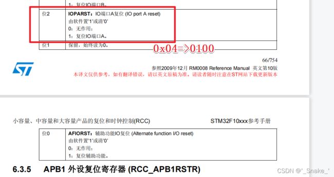
#define RCC_APB2Periph_GPIOA ((uint32_t)0x00000004)
#define RCC_APB2Periph_GPIOB ((uint32_t)0x00000008)
#define RCC_APB2Periph_GPIOC ((uint32_t)0x00000010)
#define RCC_APB2Periph_GPIOD ((uint32_t)0x00000020)
#define RCC_APB2Periph_GPIOE ((uint32_t)0x00000040)
#define RCC_APB2Periph_GPIOF ((uint32_t)0x00000080)
#define RCC_APB2Periph_GPIOG ((uint32_t)0x00000100)
#define RCC_APB2Periph_ADC1 ((uint32_t)0x00000200)
#define RCC_APB2Periph_ADC2 ((uint32_t)0x00000400)
#define RCC_APB2Periph_TIM1 ((uint32_t)0x00000800)
#define RCC_APB2Periph_SPI1 ((uint32_t)0x00001000)
#define RCC_APB2Periph_TIM8 ((uint32_t)0x00002000)
#define RCC_APB2Periph_USART1 ((uint32_t)0x00004000)
#define RCC_APB2Periph_ADC3 ((uint32_t)0x00008000)
#define RCC_APB2Periph_TIM15 ((uint32_t)0x00010000)
#define RCC_APB2Periph_TIM16 ((uint32_t)0x00020000)
#define RCC_APB2Periph_TIM17 ((uint32_t)0x00040000)
#define RCC_APB2Periph_TIM9 ((uint32_t)0x00080000)
#define RCC_APB2Periph_TIM10 ((uint32_t)0x00100000)
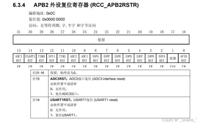
#define RCC_APB2Periph_TIM11 ((uint32_t)0x00200000)思路:先根据函数入口参数检测是要关闭哪个端口 通过RCC_APB2PeriphResetCmd(因为端口都挂载在APB2)函数进行队APB2 外设复位寄存器(RCC_APB2RSTR)的置“1”(复位IO端口A),最后在清‘0’无作用
GPIO_AFIODeInit
void GPIO_AFIODeInit(void)
{
  RCC_APB2PeriphResetCmd(RCC_APB2Periph_AFIO, ENABLE);
  RCC_APB2PeriphResetCmd(RCC_APB2Periph_AFIO, DISABLE);
}
思路:与GPIO_DeInit同理
GPIO_Init
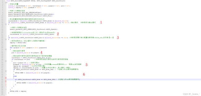
根据标号提示结合自己的理解慢慢消化
1:
主要是判断是否为输出模式,如果是输入模式的话则要把速度也写进currentmode变量,输出模式的高4位都是0001
2:
3:
判断是否为CRL寄存器所属引脚(0~7),0~7引脚低8位全是非0
4:
循环低8位引脚 找出哪个是实际配置的引脚,获取端口引脚位置,pos赋值后为当前第几个引脚,而后与实际引脚进行位与 再通过是否相当来找出端口引脚位置
5:
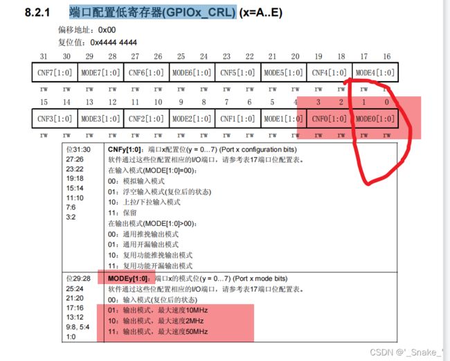
pos左移两位 实际是因为CRL寄存器配置模式+速度要用4位
6:
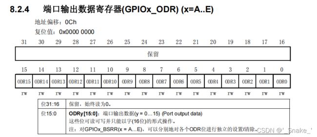
上下拉输入对应的ODR寄存器配置 BSRR和BRR寄存器都是配置ODR寄存器的
代码为CRL配置低寄存器 为不完整代码 CRH雷同
思路:代码较为复杂建议结合图文进行理解
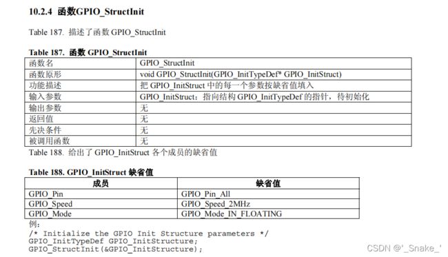
GPIO_StructInit
void GPIO_StructInit(GPIO_InitTypeDef* GPIO_InitStruct)
{
  /* Reset GPIO init structure parameters values */
  GPIO_InitStruct->GPIO_Pin  = GPIO_Pin_All;
  GPIO_InitStruct->GPIO_Speed = GPIO_Speed_2MHz;
  GPIO_InitStruct->GPIO_Mode = GPIO_Mode_IN_FLOATING;
}思路:把结构体的引脚复位为全部,速度复位为2Mhz,模式复位为浮空输入。
缺省值的意思是默认选项
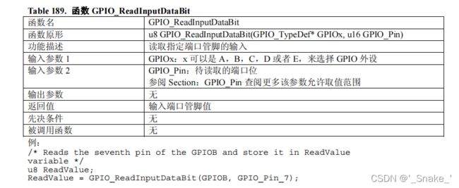
GPIO_ReadInputDataBit
uint8_t GPIO_ReadInputDataBit(GPIO_TypeDef* GPIOx, uint16_t GPIO_Pin)
{
  uint8_t bitstatus = 0x00;

  /* Check the parameters */
  assert_param(IS_GPIO_ALL_PERIPH(GPIOx));
  assert_param(IS_GET_GPIO_PIN(GPIO_Pin));

  if ((GPIOx->IDR & GPIO_Pin) != (uint32_t)Bit_RESET)
  {
    bitstatus = (uint8_t)Bit_SET;
  }
  else
  {
    bitstatus = (uint8_t)Bit_RESET;
  }
  return bitstatus;
}
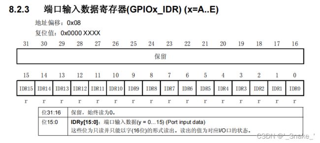
思路:读取IDR寄存器的相应位,如果不为0(Bit_RESET)则返回1。
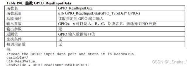
GPIO_ReadInputData
uint16_t GPIO_ReadInputData(GPIO_TypeDef* GPIOx)
{
  /* Check the parameters */
  assert_param(IS_GPIO_ALL_PERIPH(GPIOx));

  return ((uint16_t)GPIOx->IDR);
}
思路:读取IDR寄存器,以16位返回值
GPIO_ReadOutputDataBit
uint8_t GPIO_ReadOutputDataBit(GPIO_TypeDef* GPIOx, uint16_t GPIO_Pin)
{
  uint8_t bitstatus = 0x00;
  /* Check the parameters */
  assert_param(IS_GPIO_ALL_PERIPH(GPIOx));
  assert_param(IS_GET_GPIO_PIN(GPIO_Pin));

  if ((GPIOx->ODR & GPIO_Pin) != (uint32_t)Bit_RESET)
  {
    bitstatus = (uint8_t)Bit_SET;
  }
  else
  {
    bitstatus = (uint8_t)Bit_RESET;
  }
  return bitstatus;
}
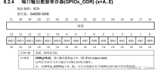
思路:读取ODR寄存器的相应位,如果不为0(Bit_RESET)则返回1。
GPIO_ReadOutputData
uint16_t GPIO_ReadOutputData(GPIO_TypeDef* GPIOx)
{
  /* Check the parameters */
  assert_param(IS_GPIO_ALL_PERIPH(GPIOx));

  return ((uint16_t)GPIOx->ODR);
}
思路:读取ODR寄存器,以16位返回值
GPIO_SetBits
void GPIO_SetBits(GPIO_TypeDef* GPIOx, uint16_t GPIO_Pin)
{
  /* Check the parameters */
  assert_param(IS_GPIO_ALL_PERIPH(GPIOx));
  assert_param(IS_GPIO_PIN(GPIO_Pin));

  GPIOx->BSRR = GPIO_Pin;
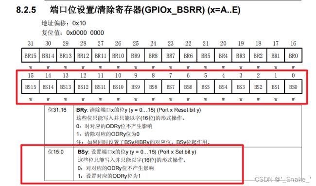
}思路:使用端口位设置/清除寄存器(GPIOx_BSRR)对相应引脚进行置‘1’,BSRR寄存器会改变ODR寄存器的值,引脚也只在0~15,除了GPIO_Pin_All
GPIO_ResetBits
void GPIO_ResetBits(GPIO_TypeDef* GPIOx, uint16_t GPIO_Pin)
{
  /* Check the parameters */
  assert_param(IS_GPIO_ALL_PERIPH(GPIOx));
  assert_param(IS_GPIO_PIN(GPIO_Pin));

  GPIOx->BRR = GPIO_Pin;
}思路:使用端口位清除寄存器(GPIOx_BRR)对相应引脚进行置‘1’从而清楚对应的ODRy为0,BRR寄存器会改ODR的值
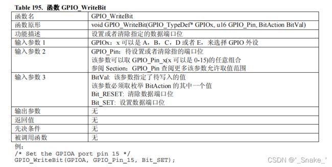
GPIO_WriteBit
void GPIO_WriteBit(GPIO_TypeDef* GPIOx, uint16_t GPIO_Pin, BitAction BitVal)
{
  /* Check the parameters */
  assert_param(IS_GPIO_ALL_PERIPH(GPIOx));
  assert_param(IS_GET_GPIO_PIN(GPIO_Pin));
  assert_param(IS_GPIO_BIT_ACTION(BitVal));

  if (BitVal != Bit_RESET)
  {
    GPIOx->BSRR = GPIO_Pin;
  }
  else
  {
    GPIOx->BRR = GPIO_Pin;
  }
}
思路:通过BSRR和BRR寄存器对相应端口和位进行配置,详情看上两个函数
GPIO_Write 
void GPIO_Write(GPIO_TypeDef* GPIOx, uint16_t PortVal)
{
  /* Check the parameters */
  assert_param(IS_GPIO_ALL_PERIPH(GPIOx));

  GPIOx->ODR = PortVal;
}
思路:对相应的端口的ODR输出寄存器,以字(16)位写入
GPIO_PinLockConfig
void GPIO_PinLockConfig(GPIO_TypeDef* GPIOx, uint16_t GPIO_Pin)
{
  uint32_t tmp = 0x00010000;

  /* Check the parameters */
  assert_param(IS_GPIO_ALL_PERIPH(GPIOx));
  assert_param(IS_GPIO_PIN(GPIO_Pin));

  tmp |= GPIO_Pin;
  /* Set LCKK bit */
  GPIOx->LCKR = tmp;
  /* Reset LCKK bit */
  GPIOx->LCKR =  GPIO_Pin;
  /* Set LCKK bit */
  GPIOx->LCKR = tmp;
  /* Read LCKK bit*/
  tmp = GPIOx->LCKR;
  /* Read LCKK bit*/
  tmp = GPIOx->LCKR;
}
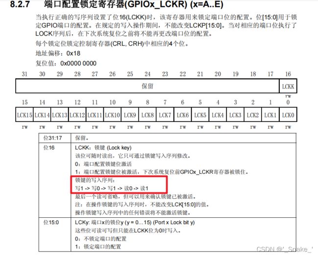
思路: 对端口配置锁定寄存器(GPIOx_LCKR),每个锁定位锁定控制寄存器(CRL, CRH)中相应的4个位,即在下次系统复位之前将不能再更改端口位的配置。
通过tmp的值与引脚相结合,然后进行锁键的写入序列: 写1 -> 写0 -> 写1 -> 读0 -> 读1
GPIO_EventOutputConfig
![]()
void GPIO_EventOutputConfig(uint8_t GPIO_PortSource, uint8_t GPIO_PinSource)
{
  uint32_t tmpreg = 0x00;
  /* Check the parameters */
  assert_param(IS_GPIO_EVENTOUT_PORT_SOURCE(GPIO_PortSource));
  assert_param(IS_GPIO_PIN_SOURCE(GPIO_PinSource));

  tmpreg = AFIO->EVCR;
  /* Clear the PORT[6:4] and PIN[3:0] bits */
  tmpreg &= EVCR_PORTPINCONFIG_MASK;            //事件端口引脚配置
  tmpreg |= (uint32_t)GPIO_PortSource << 0x04; //事件端口
  tmpreg |= GPIO_PinSource;                    //事件引脚
  AFIO->EVCR = tmpreg;
}
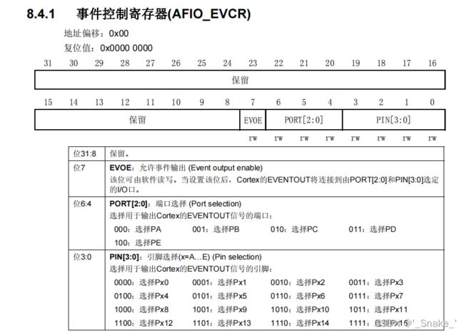
#define EVCR_PORTPINCONFIG_MASK ((uint16_t)0xFF80)思路:把AFIO_EVCR寄存器赋值给tmpreg 而后通过EVCR_PORTPINCONFIG_MASK 对位7值‘1’(允许事件输出) GPIO_PortSource(入口参数)为事件端口左位 GPIO_PinSource位事件引脚
void GPIO_EventOutputCmd(FunctionalState NewState)
{
  /* Check the parameters */
  assert_param(IS_FUNCTIONAL_STATE(NewState));

  *(__IO uint32_t *) EVCR_EVOE_BB = (uint32_t)NewState;
}
#define EVCR_EVOE_BB (PERIPH_BB_BASE + (EVCR_OFFSET * 32) + (EVOE_BitNumber * 4))思路;对EVOE进行使能
GPIO_PinRemapConfig
void GPIO_PinRemapConfig(uint32_t GPIO_Remap, FunctionalState NewState)
{
  uint32_t tmp = 0x00, tmp1 = 0x00, tmpreg = 0x00, tmpmask = 0x00;

  /* Check the parameters */
  assert_param(IS_GPIO_REMAP(GPIO_Remap));
  assert_param(IS_FUNCTIONAL_STATE(NewState));

  if((GPIO_Remap & 0x80000000) == 0x80000000)
  {
    tmpreg = AFIO->MAPR2;
  }
  else
  {
    tmpreg = AFIO->MAPR;
  }

  tmpmask = (GPIO_Remap & DBGAFR_POSITION_MASK) >> 0x10;
  tmp = GPIO_Remap & LSB_MASK;

  if ((GPIO_Remap & (DBGAFR_LOCATION_MASK | DBGAFR_NUMBITS_MASK)) == (DBGAFR_LOCATION_MASK | DBGAFR_NUMBITS_MASK))
  {
    tmpreg &= DBGAFR_SWJCFG_MASK;
    AFIO->MAPR &= DBGAFR_SWJCFG_MASK;
  }
  else if ((GPIO_Remap & DBGAFR_NUMBITS_MASK) == DBGAFR_NUMBITS_MASK)
  {
    tmp1 = ((uint32_t)0x03) << tmpmask;
    tmpreg &= ~tmp1;
    tmpreg |= ~DBGAFR_SWJCFG_MASK;
  }
  else
  {
    tmpreg &= ~(tmp << ((GPIO_Remap >> 0x15)*0x10));
    tmpreg |= ~DBGAFR_SWJCFG_MASK;
  }

  if (NewState != DISABLE)
  {
    tmpreg |= (tmp << ((GPIO_Remap >> 0x15)*0x10));
  }

  if((GPIO_Remap & 0x80000000) == 0x80000000)
  {
    AFIO->MAPR2 = tmpreg;
  }
  else
  {
    AFIO->MAPR = tmpreg;
  }
}
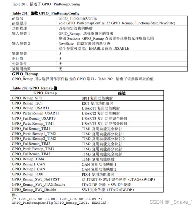
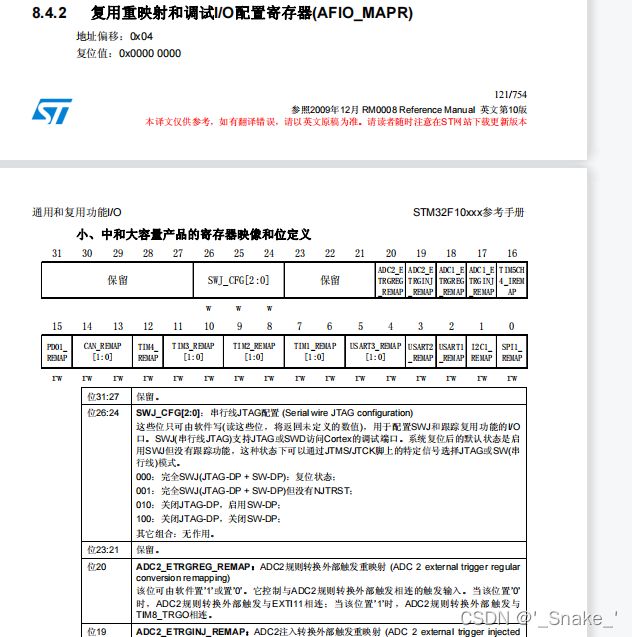
思路:对MAPR寄存器 设置,然后进行引脚的映射,重映射.部分重映射时需要用到
GPIO_EXTILineConfig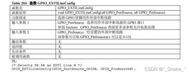
void GPIO_EXTILineConfig(uint8_t GPIO_PortSource, uint8_t GPIO_PinSource)
{
  uint32_t tmp = 0x00;
  /* Check the parameters */
  assert_param(IS_GPIO_EXTI_PORT_SOURCE(GPIO_PortSource));
  assert_param(IS_GPIO_PIN_SOURCE(GPIO_PinSource));

  tmp = ((uint32_t)0x0F) << (0x04 * (GPIO_PinSource & (uint8_t)0x03));
  AFIO->EXTICR[GPIO_PinSource >> 0x02] &= ~tmp;
  AFIO->EXTICR[GPIO_PinSource >> 0x02] |= (((uint32_t)GPIO_PortSource) << (0x04 * (GPIO_PinSource & (uint8_t)0x03)));
}
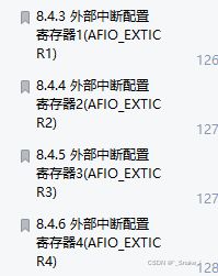
思路:对EXTICR寄存器进行外部中断的输入源引脚 进行配置
GPIO_ETH_MediaInterfaceConfig
选择以太网媒体接口,此功能仅适用于STM32连接线设备。媒体接口。
输入参数:
#define GPIO_ETH_MediaInterface_MII    ((u32)0x00000000)
#define GPIO_ETH_MediaInterface_RMII   ((u32)0x00000001)
void GPIO_ETH_MediaInterfaceConfig(uint32_t GPIO_ETH_MediaInterface)
{
assert_param(IS_GPIO_ETH_MEDIA_INTERFACE(GPIO_ETH_MediaInterface));
/* Configure MII_RMII selection bit */
*(__IO uint32_t *) MAPR_MII_RMII_SEL_BB = GPIO_ETH_MediaInterface;
}博主没有用过不太清楚 大概注解翻译已写出


