STM32F103C8T6在arduino下的例程实验
经前述环境构建好后,接下来就要跑跑例程了。
1. 串口例程
串口例程无需引用外部库
void setup() {
// initialize both serial ports:
Serial1.begin(115200);
pinMode(LED_BUILTIN, OUTPUT);
}
void loop() {
// read from port 1, send to port 0:
digitalWrite(LED_BUILTIN, HIGH); // turn the LED on (HIGH is the voltage level)
delay(1000); // wait for a second
Serial1.print("running....\n");
digitalWrite(LED_BUILTIN, LOW); // turn the LED off by making the voltage LOW
delay(1000);
}
将串口1,即PA9/PA10接到串口转换模块,打开monitor选择串口模块对应的端口,例如/dev/ttyUSB0,运行可以看到连续打印
2. WS2812驱动的幻彩RGB灯带
驱动库为stm32包自带的ws2812B.h
void setup()
{
strip.begin();// Sets up the SPI
strip.show();// Clears the strip, as by default the strip data is set to all LED's off.
// strip.setBrightness(8);
}
void loop()
{
colorWipe(strip.Color(0, 255, 0), 20); // Green
colorWipe(strip.Color(255, 0, 0), 20); // Red
colorWipe(strip.Color(0, 0, 255), 20); // Blue
rainbow(10);
rainbowCycle(10);
theaterChase(strip.Color(255, 0, 0), 20); // Red
theaterChase(strip.Color(0, 255, 0), 20); // Green
theaterChase(strip.Color(0, 0, 255), 20); // Blue
theaterChaseRainbow(10);
whiteOverRainbow(20,75,5);
pulseWhite(5);
delay(250);
fullWhite();
delay(250);
rainbowFade2White(3,3,1);
}
初始化灯阵,然后是各种特效,不得不说,简单的功能组合出来的效果不简单。
3.USB-HID设备功能开发
F103有很强大的USB功能,可是开发并不容易,在Arduino加持下,一切变得简单。
#include
USBHID HID;
HIDKeyboard Keyboard(HID);
void setup() {
HID.begin(HID_KEYBOARD);
Keyboard.begin(); // useful to detect host capslock state and LEDs
delay(1000);
}
void loop() {
Keyboard.println("Hello world");
delay(10000);
}
只需调用原装包里的composite库,然后定义为HIDKeyboard设备,就可以在插上USB 线后识别为HID设备,并发送字符串
这样的话,加上RF520模组,可以轻易自制读卡器,比如用按键选择位数,十几块搞定,太强了。
4. OLED显示屏驱动
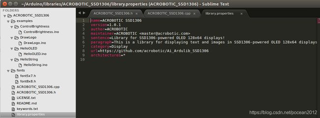
OLED 现在用的比液晶多,几乎是必备的输出显示装置,不过在这里有一点挫折,也有额外的收获,开始引用了几个驱动库,都有各种各样的问题。能用的是ACROBOTIC_SSD1306这个,也顺带了解了Arduino库的生成和导入,扩展开发等
目录结构见上图,如果需要二次开发,需要在头文件定位新的操作,在cpp里进行扩展即可。
基本的字符,图标显示都实现了,滚动研究了下,没有直接的函数实现,有机会在深入研究。
5. 运行FREERTOS 例程
创建freertos应用也是很简单,当然,例程太基础了,要完整的学习,要参考其他平台的freertos 例程,把队列,消息啥的都搞明白。
#include
static void vLEDFlashTask(void *pvParameters) {
for (;;) {
vTaskDelay(1000);
digitalWrite(LED_BUILTIN, LOW);
vTaskDelay(50);
digitalWrite(LED_BUILTIN, HIGH);
}
}
static void vPrintTask(void *pvParameters)
{int i=0;
for(;;){
i++;
Serial1.print("task2 running: ");
Serial1.print(i);
Serial1.print("...\n");
vTaskDelay(1000);}
}
void setup() {
// initialize the digital pin as an output:
pinMode(LED_BUILTIN, OUTPUT);
Serial1.begin(115200);
xTaskCreate(vLEDFlashTask,
"Task1",
configMINIMAL_STACK_SIZE,
NULL,
tskIDLE_PRIORITY + 2,
NULL);
xTaskCreate(vPrintTask,
"Task2",
configMINIMAL_STACK_SIZE,
NULL,
tskIDLE_PRIORITY + 2,
NULL);
vTaskStartScheduler();
}
void loop() {
// Insert background code here
}
这几个方面已经可以组合出很多应用了。
6.定时器中断
原装包里就有定时器中断,实测1-3可以正常使用,4编译可以通过,但不能正常使用,原因不明
/*
Timer Interrupts Example
Demonstrates usage of the HardwareTimer classes by blinking the LED
Created 22 April 2010, last updated 8 June 2010
By Bryan Newbold for LeafLabs
This code is released with no strings attached.
*/
#include
#include
#define LED_PIN PC13
//#define BUTTON_PIN 38
#define LED_RATE 500000 // in microseconds; should give 0.5Hz toggles
void handler_led(void);
void handler_count1(void);
void handler_count2(void);
int toggle = 0;
int count1 = 0;
int count2 = 0;
int int_status=0;
void setup()
{
// Set up the LED to blink
pinMode(LED_PIN, OUTPUT);
Wire.begin();
oled.init(); // Initialze SSD1306 OLED display
oled.setFont(font8x8); // Set font type (default 8x8)
oled.clearDisplay(); // Clear screen
oled.setTextXY(0,0);
oled.putString("Hello,welcome");
// Setup LED Timer
Timer2.setMode(TIMER_CH1, TIMER_OUTPUTCOMPARE);
Timer2.setPeriod(LED_RATE); // in microseconds
Timer2.setCompare(TIMER_CH1, 1); // overflow might be small
Timer2.attachInterrupt(TIMER_CH1, handler_led);
Timer1.setMode(TIMER_CH1, TIMER_OUTPUTCOMPARE);
Timer1.setPeriod(LED_RATE); // in microseconds
Timer1.setCompare(TIMER_CH1, 1); // overflow might be small
Timer1.attachInterrupt(TIMER_CH1, handler2);
// Timer4.setMode(TIMER_CH1, TIMER_OUTPUTCOMPARE);
// Timer4.setPeriod(LED_RATE*3); // in microseconds
// Timer4.setCompare(TIMER_CH1, 1); // overflow might be small
// Timer4.attachInterrupt(TIMER_CH1, handler2);
}
void loop() {
if(int_status==10){
refresh();
int_status=0;}
}
void handler_led(void) {
digitalWrite(LED_PIN,!digitalRead(LED_PIN));
// count1++;
// int_status+=1;
}
void handler1(void) {
count1++;
int_status+=1;
//refresh();
}
void handler2(void) {
count2++;
int_status+=1;
//refresh();
}
void refresh(){
Timer3.pause();
Timer4.pause();
oled.clearDisplay();
oled.setTextXY(0,0); // Set cursor position, start of line 0
oled.putString("time1: ");
oled.setTextXY(0,30);
oled.putNumber(count1);
oled.setTextXY(2,0); // Set cursor position, start of line 0
oled.putString("time2: ");
oled.setTextXY(2,30);
oled.putNumber(count2);
Timer3.resume();
Timer4.resume();
}
