ZYNQ裸板:串口篇
前言
我们在使用 PS 的时候,通常会添加 UART 控制器,用于打印信息和调试代码。除此之外, PS 在和外部设备通信时,也会经常使用串口进行通信。先从UART控制器开始讲起吧,从简单的测试再到工程实例。
UART 控制器介绍
UART 控制器是一个全双工异步收发控制器, ZYNQ 内部包含两个 UART 控制器, UART0 和 UART1。每一个 UART 控制器支持可编程的波特率发生器、 64 字节的接收 FIFO 和发送 FIFO、产生中断、 RXD 和TXD 信号的环回模式设置以及可配置的数据位长度、停止位和校验方式等。UART 控制器系统框图如下图所示:

由上图可知, UART 控制器和 IO 端口由参考时钟( UART REF_CLK)驱动,同时控制器也需要连接APB 总线时钟( CPU_1x clock), UART REF_CLK 和 CPU_1x clock 都是来自于 PS 时钟子系统。 UART 控制器的配置以及状态的获取由控制( Control)和状态寄存器( Status Registers)完成。另外, UART 控制器不仅可以连接至 MIO,也可以映射到 EMIO,从而使用 PL 的端口来实现串口通信的功能。当 UART 控制器连接到 MIO 时,只有 Tx(发送)和 Rx(接收)两个引脚;而当连接 EMIO 时,除 Tx 和 Rx 引脚外,可选的还有 CTSN、 DSDN、 DSRN 等引脚,这些引脚用于串口的流控制,即调制解调器的数据通讯中。UART 控制器采用独立的接收和发送数据路径,每个路径包含一个 64 字节的 FIFO,控制器对发送和接收 FIFO 中的数据进行串并转换操作。 FIFO 的中断标志支持轮询处理或中断驱动处理两种方式。 另外,控制器中还有一个模式开关,支持 RXD 和 TXD 信号的各种环回配置。 UART 控制器内部框图如下图所示:

UART 控制器的寄存器通过 APB 从机接口和 PS AXI 总线互联,控制器的寄存器用于对 UART 控制器进行配置和获取状态。波特率发生器( Baud Rate Generator)为 UART 控制器的接收端和发送端提供位周期时钟;中断控制器( GIC)为串口的收发提供了中断服务的功能。APB 总线接口通过向 TxFIFO 寄存器写值,将数据加载到 TxFIFO 存储器中。当数据加载至 TxFIFO 后, TxFIFO 的空标志变成无效的状态,直到最后一个数据从 TxFIFO 中移出,加载至传输移位寄存器, TxFIFO恢复空的标志位。同时 TxFIFO 使用 TFULL(满中断状态)用于表示当前 TxFIFO 已经写满,并且会阻止数据继续写入。如果此时继续执行写操作,那么会触发溢出,数据不会加载到 TxFIFO 中。RxFIFO 存储器接收来自接收移位寄存器的数据,当接收完数据后, RxFIFO 空标志信号同样变成无效的状态,直到所有的数据通过 APB 总线发送出去。 RxFIFO 的满标志状态用于表示 RxFIFO 已经写满,并且会阻止更多的数据写入。
发送FIFO与数据流
我们通过向TxFIFO寄存器写值来把数据加载到TxFIFO中。TxFIFO有空标志,FIFO中有数据时此标志无效。当TxFIFO进入完全中断状态(TFULL)时,则表明FIFO已满。此时再执行写操作,会触发溢出,数据不会加载到TxFIFO中。TxFIFO几乎满标志(TNFULL)表示FIFO中只有一个字节的空闲空间。我们可以设置门限触发器(TTRIG),当FIFO中的字节达到此值时会触发TTRIG(图示见下小节)。
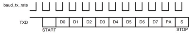
传输模块从TxFIFO中移出并行数据,将其加载到发射机移位寄存器中,实现串行化。在波特率时钟的下降沿传输数据,先传LSB,如下图:
接收FIFO与数据捕获
RxFIFO存储接收器串行移位寄存器收到的数据。RxFIFO也有与TxFIFO功能类似的空标志、完全中断状态RFUL、门限触发器RTRIG。几种标志和中断的示意如下图:

接收时,UART不断地对RxD信号进行过采样,当采样检测到一个由高到低的转换时,便将其视作起始位的开始。在波特率时钟周期的一半时,再进行三次采样,如果仍然时低电平,则认为这是一个有效的起始位。示意如下,下图是16倍的过采样:

确定了一个有效的起始位后,重新同步接收器的波特率时钟,以便在每一位的中心位置对传入的RxD信号进行采样(防止滑码),示意如下图。如果您编写过Verilog的UART收发程序,对这个处理方法应该不会感到陌生。

当确定了一个串行数据位的值后,将其转移到接收移位寄存器中。当组装好一个完整的字符后,移位寄存器中的内容被推送到RxFIFO中。
接收器错误检测
UART控制器提供了四种错误检测机制。
- 奇偶检验错误。每接收一个字符时,接收器根据UART计算接收数据位的奇偶校验值,将它与接收到的奇偶检验位进行比较。如果值不同,则奇偶校验错误标志位置1,并产生中断。
- 帧错误。当接收器在帧末没有接收到有效的停止位时,帧错误标志位置1,产生中断。
- 溢出错误。当接收到一个字符时,UART控制器检测RxFIFO是否有空间。如果有则将该字符写入RxFIFO;如果RxFIFO已满则等待;如果又检测到了下一个数据的起始位,且RxFIFO仍然是满的,那么等待的数据将丢失,同时溢出标志位置1,产生中断。
- 超时机制。接收器有一个10位的递减计数器,每当在RxD上收到一个新的起始位或者程序向专门的标志位写入1重置时,计数器都会重新加载并倒数。当计数器减到0时认定发生超时,相应标志位置1(此时程序中应重置计数器),产生中断。
上面介绍的4种中断都不是必须的,我们可以屏蔽这些中断,也可以禁用超时机制。
I/O模式选择
下图中的模式切换( Mode Switch)控制 RxD 和 TxD 的信号连接方式,总共分为四种模式,分别为:正常模式( Normal Mode)、自动回环模式( Automatic Echo Mode)、本地环回模式( Local LoopbackMode)和远程环回模式( Remote Loopback Mode)。
模式切换的功能示意图如所示:

从上图中可以清晰的看出 UART 不同模式下所实现的功能。正常模式是标准的 UART 操作模式;自动回环模式下, RxD 连接至 TxD,控制器可以接收数据,但是不能发送数据;本地环回模式没有连接 RxD 和TxD 的引脚,用于本地程序的环回测试;远程环回模式下, RxD 连接至 TxD,但是并没有和控制器连接,因此控制器在此模式下无法发送数据和接收数据。当然在实际应用中,最常用的就是 UART 的正常模式。在讲解完 UART 控制器之后,接下来我们向大家介绍程序中 UART 控制器的设计方法。如果我们只是用串口来打印信息的话,那么可以直接使用 print()或者 xil_printf()函数就可以了,无需在程序中对串口做配置。但是如果我们需要使用 UART 来完成某些特定功能的话,如串口接收中断,那么就要了解 UART 控制器初始化、 UART 中断初始化以及 UART 常用的 API 函数等相关内容了。
UART 的启动顺序
UART 的启动顺序如下:
1、 复位控制器(在 PS 系统复位时);
2、 配置 IO 引脚信号。 RxD 和 TxD 可以连接至 MIO 或者 EMIO,只有 EMIO 可以使用串口的流控制。
3、 配置 UART 参考时钟;
4、 配置控制器功能( UART 控制器初始化);
5、 配置中断,通过中断来管理 RxFIFO 和 TxFIFO;
6、 配置串口流控制(可选);
7、 管理发送和接收的数据,可以采用轮询或中断驱动处理两种方式。
配置控制器功能
控制器功能主要配置字符帧、波特率、 FIFO 触发器等级、 Rx 超时机制,并启用控制器。重置控制器后必须要配置所有这些参数。步骤如下:
1、 配置 UART 数据帧格式。如: 数据位长度、停止位、校验方式、 IO 模式等;
2、 设置波特率;
3、 设置 RxFIFO 触发器等级,可以选择启用或禁用该功能;
4、 使能 UART 控制器;
5、 配置接收器的超时机制,可以选择启用或禁用该功能。
发送数据
我们可以使用轮询或者中断两种方式控制 TxFIFO 和 RxFIFO 的数据流。这两个 FIFO 大小均为 64 个字节,因此当 TxFIFO 的空标志有效时,我们可以直接向其写入 64 个字节,无需检查 TxFIFO 的状态。实际上当发送器处于活跃状态时,可写入的字节数要超过 64 个字节,因为控制器同时也在移出数据,将其串行化转移到 TxD 信号上。
采用轮询方法发送数据的顺序如下:
1、 检查 TxFIFO 是否为空;
2、 向 TxFIFO 写入数据,可以写入 64 个字节;
3、 向 TxFIFO 中写入更多数据。我们可以等待 TxFIFO 为空之后再写入 64 个字节,即执行第 2 步;也可以检测 TxFIFO 是否写满,即不停的读取 TFUL 标志和写单个字节的数据。采用中断方法发送数据的顺序如下:
1、 禁用 TxFIFO 空中断;
2、 向 TxFIFO 写数据,可以写入 64 个字节的数据;
3、 检测 TxFIFO 是否为满状态,不停的读取 TFUL 标志和写单个字节的数据;
4、 重复步骤 2 和 3,直到 TxFIFO 已满;
5、 使能TxFIFO空中断
6、 等待,直到 TxFIFO 为空,然后从步骤 1 重新开始;
接收数据
采用轮询方法接收数据的顺序如下:
1、 等待,直到 RxFIFO 中的数据数量达到触发等级;
2、 从 RxFIFO 中读取数据;
3、 重复步骤 2 直到 FIFO 空;
4、 发生 Rx 超时中断时将其重置。
采用中断方法接收数据的顺序如下:
1、 使能中断;
2、 等待,直到 RxFIFO 中的数据数量达到触发等级或者发生超时;
3、 从 RxFIFO 中读取数据;
4、 重复步骤 2 和 3,直到 RxFIFO 为空;
5、 清除中断标志
测试代码1
下面还是代码说话吧,还是由于这次没机会用到,借鉴参考了Xilinx社区博主的代码,SDK中user_uart.h文件代码如下:
#ifndef SRC_USER_UART_H_
#define SRC_USER_UART_H_

#include "xparameters.h"
#include "xuartps.h"
#include "xil_printf.h"
#include "sleep.h"

#define UART_DEVICE_ID                  XPAR_XUARTPS_0_DEVICE_ID

int Uart_Send(XUartPs* Uart_Ps, u8 *sendbuf, int length);
int Uart_Init(XUartPs* Uart_Ps, u16 DeviceId);

#endif /* SRC_USER_UART_H_ */
user_uart.c文件的代码如下:
#include "user_uart.h"

// UART格式
XUartPsFormat uart_format =
{
	9600,
	//XUARTPS_DFT_BAUDRATE,   //默认波特率 115200
	XUARTPS_FORMAT_8_BITS,
	XUARTPS_FORMAT_NO_PARITY,
	XUARTPS_FORMAT_1_STOP_BIT,
};

//--------------------------------------------------------------
//                     UART初始化函数
//--------------------------------------------------------------
int Uart_Init(XUartPs* Uart_Ps, u16 DeviceId)
{
	int Status;
	XUartPs_Config *Config;

	/*  初始化UART设备    */
	Config = XUartPs_LookupConfig(DeviceId);
	if (NULL == Config) {
		return XST_FAILURE;
	}
	Status = XUartPs_CfgInitialize(Uart_Ps, Config, Config->BaseAddress);
	if (Status != XST_SUCCESS) {
		return XST_FAILURE;
	}

	/*  UART设备自检  */
	Status = XUartPs_SelfTest(Uart_Ps);
	if (Status != XST_SUCCESS) {
		return XST_FAILURE;
	}

	/*  设置UART模式与参数   */
	XUartPs_SetOperMode(Uart_Ps, XUARTPS_OPER_MODE_NORMAL); //正常模式
	XUartPs_SetDataFormat(Uart_Ps, &uart_format);    //设置UART格式

	return XST_SUCCESS;
}

//--------------------------------------------------------------
//                     UART数据发送函数
//--------------------------------------------------------------
int Uart_Send(XUartPs* Uart_Ps, u8 *sendbuf, int length)
{
	int SentCount = 0;

	while (SentCount < length) {
		SentCount += XUartPs_Send(Uart_Ps, &sendbuf[SentCount], 1);
	}

	return SentCount;
}
main函数如下:
#include "user_uart.h"

XUartPs Uart_Ps;		/* The instance of the UART Driver */

int main(void)
{
	int Status;
	u8 sendbuf[] = "Hello World!\r\n";
	/* 串口初始化 */
	Status = Uart_Init(&Uart_Ps, UART_DEVICE_ID);
	if (Status == XST_FAILURE) {
		xil_printf("Uartps Failed\r\n");
		return XST_FAILURE;
	}

	while (1)
	{
		sleep(1);
		Uart_Send(&Uart_Ps, sendbuf, 14);
	}

	return Status;
}
相关API函数
1.UART初始化
对UART设备初始化操作和前面GPIO设备、中断设备、定时器设备、XADC设备的初始化过程一样,不再赘述。接着使用XUartPs_SelfTest函数对UART设备自检。
s32 XUartPs_SelfTest(XUartPs *InstancePtr)
这个函数执行一次本地回环,验证可以正常发送和接受数据。返回XST_UART_TEST_FAIL表示测试失败;XST_SUCCESS表示测试成功。我们可以用这个函数检查硬件工作是否正常。
2.模式配置
初始化函数中还用XUartPs_SetOperMode函数设置了UART的工作模式。工作模式在xuartps.h文件中宏定义。
void XUartPs_SetOperMode(XUartPs *InstancePtr, u8 OperationMode)
四种工作模式的作用请参考前文。下表给出每种模式的宏定义:
| 宏定义 | 实际值 | 工作模式 |
|---|---|---|
| XUARTPS_OPER_MODE_NORMAL | 0x00U | 正常模式 |
| XUARTPS_OPER_MODE_AUTO_ECHOL | 0x01U | 自动echo模式 |
| XUARTPS_OPER_MODE_LOCAL_LOOP | 0x02U | 本地回环模式 |
| XUARTPS_OPER_MODE_REMOTE_LOOP | 0x03U | 远程回环模式 |
3.格式配置
接下来使用XUartPs_SetDataFormat函数设置UART的数据格式,包括波特率、数据位数、停止位数和奇偶校验。调用此函数时应确保UART没有收发数据。
s32 XUartPs_SetDataFormat(XUartPs *InstancePtr, XUartPsFormat * FormatPtr)
如果设置成功则返回XST_SUCCESS;如果该波特率在当前参考时钟频率下无法实现,则返回XST_UART_BAUD_ERROR表示无法设置波特率;函数的任意一个输入参数无效时返回XST_INVALI_PARAM。我们绝大多数情况下都会使用“8位数据、1位停止、无奇偶校验”,因此如果想进一步提高程序效率,可以仅使用XUartPs_SetBaudRate函数来设置波特率。
s32 XUartPs_SetBaudRate(XUartPs *InstancePtr, u32 BaudRate)
使用该函数也会检查输入的波特率值是否有效。检查的依据是xuartps.c中下面这个宏定义,即最大允许的波特率错误率:
#define XUARTPS_MAX_BAUD_ERROR_RATE 3U /* max % error allowed */
其实质上是波特率生成器产生的实际波特率与设置的波特率之间的差值。如果不满足这个条件,便会返回XST_UART_BAUD_ERROR,保持原有波特率不变。
4.数据格式
上面的函数中使用了XuartPsFormat类型的结构体来设置UART格式。该结构体原型如下:
typedef struct {
		u32 BaudRate;	/**< In bps, ie 1200 */
		u32 DataBits;	/**< Number of data bits */
		u32 Parity;		/**< Parity */
		u8 StopBits;	/**< Number of stop bits */
} XUartPsFormat;
下表总结了与数据格式相关的宏定义,使用时要将其填到结构体变量的对应位置。一般波特率可以写成数字形式,其余三个成员都要用宏定义的形式。

5.数据发送
程序中使用XUartPs_Send函数发送数据。这个函数是非阻塞的,轮询模式和中断驱动模式下都可以使用。它会尽可能地想TxFIFO填充数据,并返回发送的字节数;如果无法填充,会返回0表示发送了0字节,便于用户处理。
中断模式下,该函数会发送指定的缓冲区(Buffer)中的内容,中断处理程序负责将所有数据全部发送完。此时会调用绑定的回调函数,标识发送完成。关于中断的用法在后面文章中专门介绍。
u32 XUartPs_Send(XUartPs *InstancePtr, u8 *BufferPtr, u32 NumBytes)
第二个参数是指向要发送的数据缓冲区的指针;第三个参数是发送的字节数;返回值标识实际发送的字节数。本例程序中就是利用返回值确保所有数据都依次发送(虽然本例的数量不大,但要学习这个用法)。
这个函数还有个特殊用法,如果将第三个参数设为0,则会停止正在进行的发送操作,并将已经在TxFIFO中的所有数据都发送出去。可以用这个用法实现某些特殊功能。
一般来说,相对中断用的还是多的
测试代码2
所以更改串口驱动.h为:
#ifndef SRC_USER_UART_H_
#define SRC_USER_UART_H_

#include "xparameters.h"
#include "xuartps.h"
#include "xil_printf.h"
#include "sleep.h"
#include "xscugic.h"

#define UART_DEVICE_ID     XPAR_PS7_UART_1_DEVICE_ID //设备ID
#define UART_INT_IRQ_ID    XPAR_XUARTPS_1_INTR  //中断号
#define BUFFER_SIZE 8

int Uart_Send(XUartPs* Uart_Ps, u8 *RecvBuffer, int length);
int Uart_Init(XUartPs* Uart_Ps, u16 DeviceId);
void Uart_Intr_System(XScuGic *Intc, XUartPs *Uart_Ps, u16 UartIntrId);
void Handler(void *CallBackRef);

#endif /* SRC_USER_UART_H_ */
现在串口驱动.c为:
#include "user_uart.h"

static u8 RecvBuffer[BUFFER_SIZE];
u8 *RecvBufferPtr;
volatile u32 TotalRecvCnt;

XUartPsFormat uart_format =
{
	//9600,
	XUARTPS_DFT_BAUDRATE,   //默认波特率 115200
	XUARTPS_FORMAT_8_BITS,
	XUARTPS_FORMAT_NO_PARITY,
	XUARTPS_FORMAT_1_STOP_BIT,
};

//--------------------------------------------------------------
//                     UART初始化函数
//--------------------------------------------------------------
int Uart_Init(XUartPs* Uart_Ps, u16 DeviceId)
{
	int Status;
	XUartPs_Config *Config;

	/*  数据初始化  */
	RecvBufferPtr = RecvBuffer;
	TotalRecvCnt = 0;

	/*  初始化UART设备    */
	Config = XUartPs_LookupConfig(DeviceId);
	if (NULL == Config) {
		return XST_FAILURE;
	}
	Status = XUartPs_CfgInitialize(Uart_Ps, Config, Config->BaseAddress);
	if (Status != XST_SUCCESS) {
		return XST_FAILURE;
	}

	/*  UART设备自检  */
	Status = XUartPs_SelfTest(Uart_Ps);
	if (Status != XST_SUCCESS) {
		return XST_FAILURE;
	}

	/*  设置UART模式与参数   */
	XUartPs_SetOperMode(Uart_Ps, XUARTPS_OPER_MODE_NORMAL); //正常模式
	XUartPs_SetDataFormat(Uart_Ps, &uart_format);    //设置UART格式
	XUartPs_SetFifoThreshold(Uart_Ps, 8);  //设置RxFIFO的中断触发等级

	return XST_SUCCESS;
}

//--------------------------------------------------------------
//                  UART中断系统初始化函数
//--------------------------------------------------------------
void Uart_Intr_System(XScuGic *Intc, XUartPs *Uart_Ps, u16 UartIntrId)
{
	XScuGic_Connect(Intc, UartIntrId,
			(Xil_ExceptionHandler) Handler,
			(void *) Uart_Ps);
	XScuGic_Enable(Intc, UartIntrId);
	// 设置UART的中断触发方式
	XUartPs_SetInterruptMask(Uart_Ps, XUARTPS_IXR_RXOVR);
}

//--------------------------------------------------------------
//                     UART中断处理函数
//--------------------------------------------------------------
void Handler(void *CallBackRef)
{
	XUartPs *UartInstancePtr = (XUartPs *) CallBackRef ;
	u32 ReceivedCount = 0 ;
	u32 IsrStatus ;

	//读取中断ID寄存器,判断触发的是哪种中断
	IsrStatus = XUartPs_ReadReg(UartInstancePtr->Config.BaseAddress,
				   XUARTPS_IMR_OFFSET);
	IsrStatus &= XUartPs_ReadReg(UartInstancePtr->Config.BaseAddress,
				   XUARTPS_ISR_OFFSET);

	if (IsrStatus & (u32)XUARTPS_IXR_RXOVR)   /* 检查RxFIFO是否触发 */
	{
		ReceivedCount = XUartPs_Recv(UartInstancePtr, RecvBufferPtr, (BUFFER_SIZE-TotalRecvCnt)) ;
		TotalRecvCnt += ReceivedCount ;
		RecvBufferPtr += ReceivedCount ;
		/* 清除中断标志 */
		XUartPs_WriteReg(UartInstancePtr->Config.BaseAddress, XUARTPS_ISR_OFFSET, XUARTPS_IXR_RXOVR) ;
	}

	xil_printf("Enter INTR\r\n");
	/* 数据处理 */
	if (TotalRecvCnt >= BUFFER_SIZE) {
		xil_printf("%s", RecvBuffer);
		xil_printf("\r\nI have received %d bytes.\r\n", TotalRecvCnt);
		RecvBufferPtr = RecvBuffer;
		TotalRecvCnt = 0;
	}
}
现在的main函数为:
#include "sys_intr.h"
#include "user_uart.h"

XScuGic Intc;       //GIC
XUartPs Uart_Ps;	//UART

void System_Init(void)
{
	Init_Intr_System(&Intc);
	Setup_Intr_Exception(&Intc);
	Uart_Intr_System(&Intc, &Uart_Ps, UART_INT_IRQ_ID);
}

int main(void)
{
	int Status;

	/* 串口初始化 */
	Status = Uart_Init(&Uart_Ps, UART_DEVICE_ID);
	if (Status == XST_FAILURE) {
		xil_printf("Uartps Failed\r\n");
		return XST_FAILURE;
	}
	System_Init();   //中断初始化
	while (1){
		sleep(1);
		xil_printf("Hello World!\r\n");
	}
	return Status;
}
不过很遗憾,在这段时间基本没这么认真地配置过PS端的串口,基本都用来调试打印了。PL端通过UartLite或者UartNs550相对用的较多一点(因为要用的串口实在是太多了,不论是作为串口服务器还是作为各种交互)算了还是直接代码说话吧
工程代码
先是头文件,FIFO部分参考万能的FIFO篇
#ifndef SRC_UART_DRIVER_H_
#define SRC_UART_DRIVER_H_
#include "xparameters.h"
#include "xuartns550.h"
#include "xil_exception.h"
#ifdef XPAR_INTC_0_DEVICE_ID
#include "xintc.h"
#include 再然后是驱动函数了
#include "Uart_driver.h"


u8 SendBuffer[FIFO_SIZE];	/* Buffer for Transmitting Data */


/*
 * The following counters are used to determine when the entire buffer has
 * been sent and received.
 */
//static volatile int TotalReceivedCount;
 int TotalReceivedCount;
static volatile int TotalSentCount;
static volatile int TotalErrorCount;


#ifndef TESTAPP_GEN

#endif

/*****************************************************************************/
/**
*
* This function does a minimal test on the UartNs550 device and driver as a
* design example. The purpose of this function is to illustrate how to use the
* XUartNs550 component.
*
* This function transmits data and expects to receive the same data through the
* UART using the local loopback of the hardware.
*
* This function uses interrupt driver mode of the UART.
*
* @param	IntcInstancePtr is a pointer to the instance of the
*		Interrupt Controller.
* @param	UartInstancePtr is a pointer to the instance of the UART .
* @param	UartDeviceId is the device Id and is typically
*		XPAR__DEVICE_ID value from  xparameters.h.
* @param	UartIntrId is the interrupt Id and is typically
*		XPAR___IP2INTC_IRPT_INTR
*		value from xparameters.h.
*
* @return	XST_SUCCESS if successful, otherwise XST_FAILURE.
*
* @note
*
* This function contains an infinite loop such that if interrupts are not
* working it may never return.
*
*******************************************************************************/
int UartNs550Init(INTC *IntcInstancePtr,
			XUartNs550 *UartInstancePtr,
			u16 UartDeviceId,
			u16 UartIntrId)
{
	int Status;
	u32 Index;
	u16 Options;
	u32 BadByteCount = 0;
	XUartNs550_Handler CB;


	/*
	 * Initialize the UART driver so that it's ready to use.
	 */
	Status = XUartNs550_Initialize(UartInstancePtr, UartDeviceId);
	if (Status != XST_SUCCESS) {
		return XST_FAILURE;
	}

	/*
	 * Perform a self-test to ensure that the hardware was built correctly.
	 */
	/*Status = XUartNs550_SelfTest(UartInstancePtr);
	if (Status != XST_SUCCESS) {
		return XST_FAILURE;
	}*/

	/*
	 * Connect the UART to the interrupt subsystem such that interrupts can
	 * occur. This function is application specific.
	 */
	Status = UartNs550SetupIntrSystem(IntcInstancePtr,
						UartInstancePtr,
						UartIntrId);
	if (Status != XST_SUCCESS) {
		return XST_FAILURE;
	}

	/*
	 * Setup the handlers for the UART that will be called from the
	 * interrupt context when data has been sent and received, specify a
	 * pointer to the UART driver instance as the callback reference so
	 * the handlers are able to access the instance data.
	 */

	switch(UartDeviceId)
	{
	case XPAR_UARTNS550_0_DEVICE_ID:
		CB = Uart0Ns550IntrHandler;
		break;

	default:
		break;

	}

	XUartNs550_SetHandler(UartInstancePtr, CB,
				  UartInstancePtr);

	/*
	 * Enable the interrupt of the UART so interrupts will occur, setup
	 * a local loopback so data that is sent will be received, and keep the
	 * FIFOs enabled.
	 */
	Options = XUN_OPTION_DATA_INTR | //得把例程的回环屏蔽XUN_OPTION_LOOPBACK |
			XUN_OPTION_FIFOS_ENABLE;
	XUartNs550_SetOptions(UartInstancePtr, Options);


	/*
	 * Initialize the send buffer bytes with a pattern to send and the
	 * the receive buffer bytes to zero to allow the receive data to be
	 * verified.
	 */
//	for (Index = 0; Index < TEST_BUFFER_SIZE; Index++) {
//		SendBuffer[Index] = Index + 'A';
//		RecvBuffer[Index] = 0;
//	}

	/*
	 * Start receiving data before sending it since there is a loopback,
	 * ignoring the number of bytes received as the return value since we
	 * know it will be zero and we are using interrupt mode.
	 */
	// XUartNs550_Recv(UartInstancePtr, RecvBuffer, TEST_BUFFER_SIZE);
//多好的现成的接收函数

	/*
	 * Send the buffer using the UART and ignore the number of bytes sent
	 * as the return value since we are using it in interrupt mode.
	 */
	// XUartNs550_Send(UartInstancePtr, SendBuffer, TEST_BUFFER_SIZE);
//哟呵还有发送呢齐活了
	/*
	 * Wait for the entire buffer to be received, letting the interrupt
	 * processing work in the background, this function may get locked
	 * up in this loop if the interrupts are not working correctly.
	 */
//	while ((TotalReceivedCount != TEST_BUFFER_SIZE) ||
//		(TotalSentCount != TEST_BUFFER_SIZE)) {
//	}
//
//	/*
//	 * Verify the entire receive buffer was successfully received.
//	 */
//	for (Index = 0; Index < TEST_BUFFER_SIZE; Index++) {
//		if (RecvBuffer[Index] != SendBuffer[Index]) {
//			BadByteCount++;
//		}
//	}

	/*
	 * Disable the UartNs550 interrupt.
	 */
	 //UartNs550DisableIntrSystem(IntcInstancePtr, UartIntrId);


	/*
	 * If any bytes were not correct, return an error.
	 */
//	if (BadByteCount != 0) {
//		return XST_FAILURE;
//	}
//
//	/* Clear the counters */
//	TotalErrorCount = 0;
//	TotalReceivedCount = 0;
//	TotalSentCount = 0;
//
return XST_SUCCESS;
}

/*****************************************************************************/
/**
*
* This function is the handler which performs processing to handle data events
* from the UartNs550.  It is called from an interrupt context such that the
* amount of processing performed should be minimized.
*
* This handler provides an example of how to handle data for the UART and
* is application specific.
*
* @param	CallBackRef contains a callback reference from the driver,
*		in thiscase it is the instance pointer for the UART driver.
* @param	Event contains the specific kind of event that has occurred.
* @param	EventData contains the number of bytes sent or received for sent
*		and receive events.
*
* @return	None.
*
* @note		None.
*
*******************************************************************************/
void Uart0Ns550IntrHandler(void *CallBackRef, u32 Event, unsigned int EventData)
{
	u8 Errors;
	XUartNs550 *UartNs550Ptr = (XUartNs550 *)CallBackRef;
    u8 recData[256];

	/*
	 * All of the data has been sent.
	 */
	if (Event == XUN_EVENT_SENT_DATA) {
		TotalSentCount = EventData;
	}

	/*
	 * All of the data has been received.
	 */
	if (Event == XUN_EVENT_RECV_DATA)
	{

		TotalReceivedCount = EventData;

		//xil_printf("d-\r\n");
		///XUartNs550_Recv(&Uart0Ns550Instance, recData, 10);
		//FifoWrite(&Uart0FIFO,recData,10);
	}

	/*
	 * Data was received, but not the expected number of bytes, a
	 * timeout just indicates the data stopped for 4 character times.
	 */
	if (Event == XUN_EVENT_RECV_TIMEOUT) {
		TotalReceivedCount = EventData;
		//xil_printf("c-\r\n");

	}

	/*
	 * Data was received with an error, keep the data but determine
	 * what kind of errors occurred.
	 */
	if (Event == XUN_EVENT_RECV_ERROR) {
		TotalReceivedCount = EventData;
		TotalErrorCount++;
		Errors = XUartNs550_GetLastErrors(UartNs550Ptr);
		//xil_printf("c1-\r\n");
	}


	//xil_printf("TotalReceivedCount=%d\r\n",TotalReceivedCount);
	//xil_printf("TotalErrorCount=%d\r\n",TotalErrorCount);

}

/*****************************************************************************/
/**
*
* This function is the handler which performs processing to handle data events
* from the UartNs550.  It is called from an interrupt context such that the
* amount of processing performed should be minimized.
*
* This handler provides an example of how to handle data for the UART and
* is application specific.
*
* @param	CallBackRef contains a callback reference from the driver,
*		in thiscase it is the instance pointer for the UART driver.
* @param	Event contains the specific kind of event that has occurred.
* @param	EventData contains the number of bytes sent or received for sent
*		and receive events.
*
* @return	None.
*
* @note		None.
*
*******************************************************************************/

/******************************************************************************/
/**
*
* This function setups the interrupt system such that interrupts can occur
* for the UART.  This function is application specific since the actual
* system may or may not have an interrupt controller.  The UART could be
* directly connected to a processor without an interrupt controller.  The
* user should modify this function to fit the application.
*
* @param	IntcInstancePtr is a pointer to the instance of the Interrupt
*		Controller.
* @param	UartInstancePtr is a pointer to the instance of the UART.
* @param	UartIntrId is the interrupt Id and is typically
*		XPAR___VEC_ID value from
*		xparameters.h.
*
* @return	XST_SUCCESS if successful, otherwise XST_FAILURE.
*
* @note		None.
*
*******************************************************************************/
static int UartNs550SetupIntrSystem(INTC *IntcInstancePtr,
					XUartNs550 *UartInstancePtr,
					u16 UartIntrId)
{
	int Status;

#else
#ifndef TESTAPP_GEN
	XScuGic_Config *IntcConfig;

	/*
	 * Initialize the interrupt controller driver so that it is ready to
	 * use.
	 */
	IntcConfig = XScuGic_LookupConfig(INTC_DEVICE_ID);
	if (NULL == IntcConfig) {
		return XST_FAILURE;
	}

	Status = XScuGic_CfgInitialize(IntcInstancePtr, IntcConfig,
					IntcConfig->CpuBaseAddress);
	if (Status != XST_SUCCESS) {
		return XST_FAILURE;
	}
#endif /* TESTAPP_GEN */

	XScuGic_SetPriorityTriggerType(IntcInstancePtr, UartIntrId,
					0xA0, 0x3);

	/*
	 * Connect the interrupt handler that will be called when an
	 * interrupt occurs for the device.
	 */
	Status = XScuGic_Connect(IntcInstancePtr, UartIntrId,
				 (Xil_ExceptionHandler)XUartNs550_InterruptHandler,
				 UartInstancePtr);
	if (Status != XST_SUCCESS) {
		return Status;
	}

	/*
	 * Enable the interrupt for the Timer device.
	 */
	XScuGic_Enable(IntcInstancePtr, UartIntrId);
#endif /* XPAR_INTC_0_DEVICE_ID */

#ifndef TESTAPP_GEN

	/*
	 * Initialize the exception table.
	 */
	Xil_ExceptionInit();

	/*
	 * Register the interrupt controller handler with the exception table.
	 */
	Xil_ExceptionRegisterHandler(XIL_EXCEPTION_ID_INT,
			 (Xil_ExceptionHandler)INTC_HANDLER,
			 IntcInstancePtr);

	/*
	 * Enable exceptions.
	 */
	Xil_ExceptionEnable();

#endif /* TESTAPP_GEN */

	return XST_SUCCESS;
}


static void UartNs550DisableIntrSystem(INTC *IntcInstancePtr, u16 UartIntrId)
{

	/*
	 * Disconnect and disable the interrupt for the UartNs550 device.
	 */
#ifdef XPAR_INTC_0_DEVICE_ID
	XIntc_Disconnect(IntcInstancePtr, UartIntrId);
#else
	XScuGic_Disable(IntcInstancePtr, UartIntrId);
	XScuGic_Disconnect(IntcInstancePtr, UartIntrId);

#endif


}
下面写主函数,嗯便于工程移植直接写个demo直接调用吧
void Uart_demo()
{
	int i,Status;
	u8 sendbuf[] = "HelloWorld";
	u8 recvbuf[FIFO_SIZE] = {};
//多余的自己复制粘贴吧
	FifoInit(&Uart0FIFO,&RecvBuffer[0],FIFO_SIZE);
//多余的自己复制粘贴吧		/*
	 * Run the UartNs550 Interrupt example.
	 */
	Status = UartNs550Init(&IntcInstance0,
					&Uart0Ns550Instance,
					XPAR_UARTNS550_0_DEVICE_ID,
					XPAR_FABRIC_AXI_UART16550_0_IP2INTC_IRPT_INTR);
	XUartNs550_SetBaudRate(&Uart0Ns550Instance,115200); //多余的自己复制粘贴吧,这可是个好东西,可以单独设置波特率,不然就是默认的了,默认的也可以直接填
	if (Status != XST_SUCCESS)
	{
		xil_printf("Uartns550 0 interrupt Example Failed\r\n");
		return XST_FAILURE;
	}


  //多余的自己复制粘贴吧
	//XUartNs550_Send(&UartNs550Instance, sendbuf, 14);
	//XUartNs550_Recv(&UartNs550Instance, recvbuf, TEST_BUFFER_SIZE);
	//XUartNs550_Recv(&UartNs550Instance, recvbuf, 8);

		//XUartNs550_Recv(&Uart0Ns550Instance, recvbuf, 1);

	XUartNs550_Recv(&Uart0Ns550Instance, recvbuf, 256);
	//多余的自己复制粘贴吧
	while(1)
	{
		sleep(1);

		//FifoRead(&Uart0FIFO,recvbuf,40);
//因为不知名bug原因暂时屏蔽掉,多余的自己复制粘贴吧			//XUartNs550_ReadReg(XPAR_UARTNS550_0_BASEADDR,0x1000);
	    XUartNs550_Send(&Uart0Ns550Instance, sendbuf, 10);
	   //多余的自己复制粘贴吧
		if(TotalReceivedCount > 0)
		{
			XUartNs550_Recv(&Uart0Ns550Instance, recvbuf, 256);
			//多余的自己复制粘贴吧				//FifoWrite(&Uart0FIFO,recvbuf,256);
			TotalReceivedCount = 0;
		}

		for(int i=0; i < 20; i++)
		  {xil_printf("%c ",recvbuf[i]);}
		   xil_printf("\r\n");
		//多余的自己复制粘贴吧
		    	xil_printf("\n\r");
		for(int i=0; i < 20; i++)
//			{xil_printf("%c ",recvbuf11[i]);}
//				xil_printf("\n\r");
		memset(recvbuf,0,256);
//多余的自己复制粘贴吧
	}

}
先写这么多了,目前只了解到这些,之后串口服务器篇在补充一些Linux移植后的代码吧
学习zynq时间较短,认知有限,代码也比较简陋。如有错误欢迎批评指正。影响阅读的图片水印也已去掉欢迎大家收藏
参考:芯片手册 原子开发手册 CSDN Xilinx社区等网络资源