图像拼接(七):OpenCV单应变换模型拼接多幅图像
上篇博客图像拼接(六):OpenCV单应变换模型拼接两幅图像 实现了两幅图像的拼接,主要是使用了单应矩阵和warpPerspective()这个库函数。
#求取每相邻两幅图像的单应矩阵
拼接多幅图像,需要计算每相邻两幅图像的单应矩阵,上篇已经封装了求取单应矩阵的类,可以拿来用。
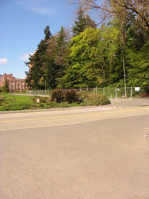
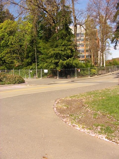
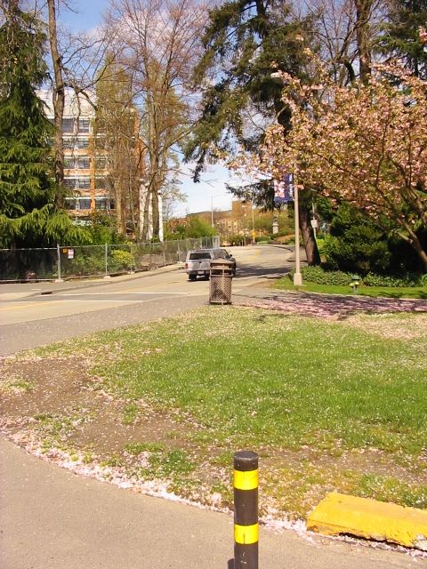
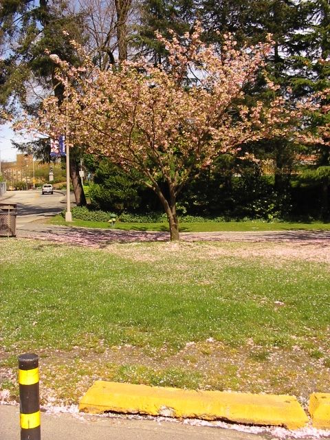
现有4幅图像: i m g 1 img1 img1, i m g 2 img2 img2, i m g 3 img3 img3, i m g 4 img4 img4。依次从右向左排列,拼接图像以最左侧的 i m g 4 img4 img4为参考图像。
Homography homo12(img1,img2);
Homography homo23(img2, img3);
Homography homo34(img3, img4);

Mat h12 = homo12.getHomography();
Mat h23 = homo23.getHomography();
Mat h34 = homo34.getHomography();
#透视变换
warpPerspective(InputArray src, OutputArray dst, InputArray M, Size dsize)
这个函数却显得不够灵活。一方面,目标投影的图像不能够选取兴趣区域,使得每拼接两幅都会产生一个结果图像;另一方面,投影参考原点为图像左上角,如果投影后的图像在左方,就不能显示出,所以需要左侧的图像为参考图像。
为了实现方便,拼接4幅图像以最左侧图像作为参考(其实这种方案会产生累加误差和图像变形,最佳的方案应该是选择中间幅作为参考基准),计算其余3幅图像到它的变换。
	Mat h24 = h34*h23;
	Mat h14 = h24*h12;

	float scale_h24 = h24.at<double>(2, 2);
	float scale_h14 = h14.at<double>(2, 2);
	h24 = h24 / scale_h24;
	h14 = h14 / scale_h14;

	Mat warp1;
	warpPerspective(img1_color, warp1, h14, Size(img1.cols * 4, img1.rows));
	Mat warp2;
	warpPerspective(img2_color, warp2, h24, Size(img1.cols * 4, img1.rows));
	Mat warp3;
	warpPerspective(img3_color, warp3, h34, Size(img1.cols * 4, img1.rows));
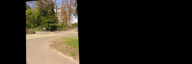
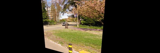
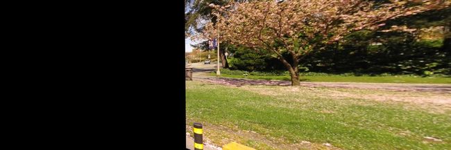
投影结果:
再把上述中间结果放在一个最终的结果图像中。怎么自动地确定水平方向剪切的边界呢?我的一个解决思路是:根据单应矩阵的8个参数,提取出水平位移量。将单应变换公式展开
$\begin{bmatrix} x^\prime \ y^\prime \1 \end{bmatrix} =\begin{bmatrix} 1+h_{00} &h_{01} & h_{02} \ h_{10} & 1+h_{11}&h_{12} \h_{20}&h_{21}&1 \end{bmatrix} \begin{bmatrix} x \ y \1 \end{bmatrix} $
x ′ = ( 1 + h 00 ) x + h 01 y + h 02 h 20 x + h 21 y + 1 x^\prime=\dfrac{(1+h_{00})x+h_{01}y+h_{02}}{h_{20}x+h_{21}y+1} x′=h20x+h21y+1(1+h00)x+h01y+h02
对不同的 x x x和 y y y,位移量不同,不可能提取出一个统一的值。这里采取粗略的方式,取 x = 0 x=0 x=0和 y = 0 y=0 y=0时得出的 x ′ x^\prime x′值作为水平位移量。因为在边缘剪容易出现黑色像素,所以再加上 2 5 \frac{2}{5} 52原始图像宽度,选取大概靠图像中间的位置作为剪切位置。当然这个中间位置的计算是及其粗略的,但至少避开了边缘。
剪切代码
	int d = img1.cols*2/5;

	int x3 = h34.at<double>(0,2)+d;
	int x2 = x3 + h23.at<double>(0, 2);
	int x1 = x2 + h12.at<double>(0, 2);

	Mat canvas(img1.rows,img1.cols*4,CV_8UC3);
	img4_color.copyTo(canvas(Range::all(), Range(0, img1.cols)));
	warp3(Range::all(), Range(x3, x2)).copyTo(canvas(Range::all(), Range(x3, x2)));
	warp2(Range::all(), Range(x2, x1)).copyTo(canvas(Range::all(), Range(x2, x1)));
	warp1(Range::all(), Range(x1, x1 + img1.cols)).copyTo(canvas(Range::all(), Range(x1, x1 + img1.cols)));
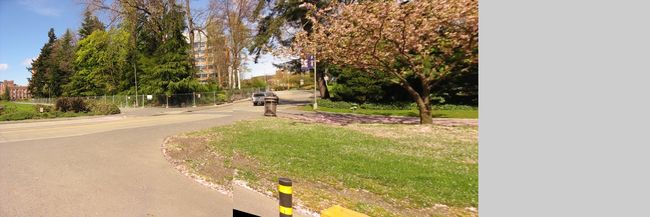
最终结果
由拼接结果可以看出,图像越往右侧,图像变形越大,出现了明显的拼接误差,这个可以通过后期融合来消除。另一方面,由于接缝位置选择不当,第4张图像只显示了一部分和出现了不对齐的情况,可以采用最佳拼接缝算法,使不对齐的情况最小化。本篇博客未实现接缝融合和最佳拼接缝寻找。
#完整代码和图像素材
#include"Homography.h"

int main()
{
	//从右向左升序
	string imgPath1 = "trees_003.jpg";
	string imgPath2 = "trees_002.jpg";
	string imgPath3 = "trees_001.jpg";
	string imgPath4 = "trees_000.jpg";

	Mat img1 = imread(imgPath1, CV_LOAD_IMAGE_GRAYSCALE);
	Mat img2 = imread(imgPath2, CV_LOAD_IMAGE_GRAYSCALE);
	Mat img3 = imread(imgPath3, CV_LOAD_IMAGE_GRAYSCALE);
	Mat img4 = imread(imgPath4, CV_LOAD_IMAGE_GRAYSCALE);

	Mat img1_color = imread(imgPath1, CV_LOAD_IMAGE_COLOR);
	Mat img2_color = imread(imgPath2, CV_LOAD_IMAGE_COLOR);
	Mat img3_color = imread(imgPath3, CV_LOAD_IMAGE_COLOR);
	Mat img4_color = imread(imgPath4, CV_LOAD_IMAGE_COLOR);

	Homography homo12(img1,img2);
	Homography homo23(img2, img3);
	Homography homo34(img3, img4);

	Mat h12 = homo12.getHomography();
	Mat h23 = homo23.getHomography();
	Mat h34 = homo34.getHomography();

	/*homo12.drawMatches();
	homo23.drawMatches();
	homo34.drawMatches();*/

	Mat h24 = h34*h23;
	Mat h14 = h24*h12;

	float scale_h24 = h24.at<double>(2, 2);
	float scale_h14 = h14.at<double>(2, 2);
	h24 = h24 / scale_h24;
	h14 = h14 / scale_h14;

	Mat warp1;
	warpPerspective(img1_color, warp1, h14, Size(img1.cols * 4, img1.rows));
	Mat warp2;
	warpPerspective(img2_color, warp2, h24, Size(img1.cols * 4, img1.rows));
	Mat warp3;
	warpPerspective(img3_color, warp3, h34, Size(img1.cols * 4, img1.rows));

	imshow("warp1", warp1);
	imshow("warp2",warp2);
	imshow("warp3", warp3);

	imwrite("warp1.jpg", warp1);
	imwrite("warp2.jpg", warp2);
	imwrite("warp3.jpg", warp3);

	int d = img1.cols*2/5;
	int x3 = h34.at<double>(0,2)+d;
	int x2 = x3 + h23.at<double>(0, 2);
	int x1 = x2 + h12.at<double>(0, 2);

	Mat canvas(img1.rows,img1.cols*4,CV_8UC3);
	img4_color.copyTo(canvas(Range::all(), Range(0, img1.cols)));
	warp3(Range::all(), Range(x3, x2)).copyTo(canvas(Range::all(), Range(x3, x2)));
	warp2(Range::all(), Range(x2, x1)).copyTo(canvas(Range::all(), Range(x2, x1)));
	warp1(Range::all(), Range(x1, x1 + img1.cols)).copyTo(canvas(Range::all(), Range(x1, x1 + img1.cols)));


	imwrite("canvas.jpg",canvas);
	imshow("canvas",canvas);

	waitKey(0);
	return 0;
}
