三维激光点云到二维图像的投影
Camera系列文章
传感器融合是将多个传感器采集的数据进行融合处理,以更好感知周围环境;这里首先介绍Camera的相关内容,包括摄像头及图像知识基本介绍,OpenCV图像识别(特征提取,目标分类等),融合激光点云和图像进行TTC估计。
系列文章目录
1. 摄像头基础及校准
2. Lidar TTC估计
3. Camera TTC估计
4. OpenCV图像特征提取
5. 常见特征检测算法介绍
6. 常见特征描述符介绍
7. YOLOv3物体检测
8. 三维激光点云到二维图像的投影
文章目录
- Camera系列文章
- 前言
- 齐次坐标系
- 内外参(Intrinsic and Extrinsic Parameters)
-
- 内参
- 外参
- KITTI传感器配置
- 激光点云到摄像头图像的投影
前言
我们可以使用摄像头或激光雷达跟踪物体。单一传感器的主要问题是,每个传感器都有其弱点,某些场景可能会可靠性降低,因此需要恰当的融合摄像头和激光雷达以提升跟踪过程效果。
本章中将介绍如何融合3D激光雷达点云数据和摄像头跟踪的特征点——将激光点云投影到Camera图像上。
齐次坐标系
相机坐标系下,3D空间点 P ⃗ \vec{P} P到图像坐标系中 P ′ ⃗ \vec{P'} P′的映射公式如下:

除了上述针孔相机模型几何投影对应的摄像头内参,也需要摄像头和雷达在同一坐标系下的相对位置和方位关系。激光雷达到摄像头的转换包含对每个点进行平移和旋转操作。使用线性变换(映射),3D点使用向量表示,旋转、平移、缩放操作、透视变换使用对向量的矩阵乘表示。3D空间点到2D图像的变换会丢掉Z轴(距离)信息,导致非线性,通常解决办法是引入齐次坐标系(Homogenous coordinate system)替代原有的欧氏坐标系(Euclidean coordinate system),如下所示,通过简答的矩阵-向量乘即可实现,具体如下:

内外参(Intrinsic and Extrinsic Parameters)
内参
以下是针孔摄像头模型的投影方程。

内参矩阵K的参数对成像的影响可参考如下网站:Dissecting the Camera Matrix, Part 3: The Intrinsic Matrix
外参
目前我们讨论了摄像头坐标系中的3D空间点P到2D图像平面的映射。但通常有多个传感器,每个传感器都有各自的坐标系,同时还有车辆坐标系。如下图所示,车辆坐标系的坐标原点位于后轴中心点的地面上,X轴指向行车方向,Y轴指向车辆左侧,Z轴向上,符合右手定则。围绕X、Y、Z的旋转为roll, pitch,yaw。

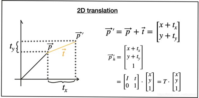
当车辆同时配备激光雷达和摄像头时,就需要进行坐标系变换(映射),通常包括:①平移(如下图所示, P ⃗ \vec{P} P→ P ′ ⃗ \vec{P'} P′),使用平移向量 t ⃗ \vec{t} t。齐次坐标系中,可以使用N*N的单位矩阵I和平移向量 t ⃗ \vec{t} t拼接得到矩阵T。其中N为 P ⃗ \vec{P} P元素个数。

②缩放因子,在其次坐标系中为 s ⃗ \vec{s} s

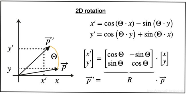
③旋转矩阵R: P ′ ⃗ \vec{P'} P′逆时针方向旋转为正。


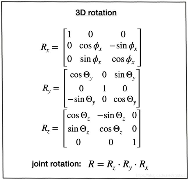
绕X、Y、Z轴的旋转可以用旋转矩阵R表示, R = R z ⋅ R y ⋅ R x R =R_z \cdot R_y \cdot R_x R=Rz⋅Ry⋅Rx。
齐次坐标系的一大好处是可以通过拼接矩阵-向量乘实现多个矩阵乘的组合矩阵。
旋转矩阵R和平移向量 t ⃗ \vec{t} t也称外参,指示点在不同坐标系的转换。实现从激光雷达坐标系到摄像头坐标系的转换后,还需要映射到图像平面上,因此还需要合并内参矩阵,齐次坐标系中变换如下。线性因子已合并只内参矩阵K中(焦距为相关参数)

外参对物体成像的影响可参考如下网站:Perspective Camera Toy
KITTI传感器配置
本章中我们将使用KITTI数据集生成数据流,因此下面介绍KITTI车辆传感器配置及其坐标。KITTI采集车如下,配置2个前视摄像头,1个车顶Velodyne激光雷达(带IMU)。
对于所有数据集,内外参校准文件都可以从KITTI网站下载。如下为“calib_velo_to_cam.txt”文件,Velodyne到左前摄像头的坐标变换矩阵,即外参。
calib_time: 15-Mar-2012 11:37:16
R: 7.533745e-03 -9.999714e-01 -6.166020e-04 1.480249e-02 7.280733e-04 -9.998902e-01 9.998621e-01 7.523790e-03 1.480755e-02
T: -4.069766e-03 -7.631618e-02 -2.717806e-01
…
为实现激光点云到摄像头图像的投影,也需要内参矩阵,存储在"calib_cam_to_cam.txt",如下:
calib_time: 09-Jan-2012 13:57:47
…
R_rect_00: 9.999239e-01 9.837760e-03 -7.445048e-03 -9.869795e-03 9.999421e-01 -4.278459e-03 7.402527e-03 4.351614e-03 9.999631e-01
P_rect_00: 7.215377e+02 0.000000e+00 6.095593e+02 0.000000e+00 0.000000e+00 7.215377e+02 1.728540e+02 0.000000e+00 0.000000e+00 0.000000e+00 1.000000e+00 0.000000e+00
…
R_rect_00是3*3旋转校准,使图像平面共面,即对齐两个摄像头,左摄像头的一行像素对齐右侧摄像头的一行像素。P_rect_00包含摄像头内参(K),以下是3D激光点云的空间点 X到左摄像头2D图像点Y的坐标变换。
Y=P_rect_XX * R_rect_00 * (R|T)_velo_to_cam * X
激光点云到摄像头图像的投影
void projectLidarToCamera2()
{
  //load image from file
  cv::Mat img = cv::imread("./images/00000000.png");

  //load lidar points from file
  std::vector<LidarPoint> lidarPoints;
  readLidarPts("./dat/C51_LidarPts_0000.dat",lidarPoints);

  //store calibration data in Opencv matrices
  cv::Mat P_rect_00(3,4,cv::DataType<double>::type);//3×4 projection matrix after rectification
  cv::Mat R_rect_00(4,4,cv::DataType<double>::type);//3×3 rectifying rotation to make image planes co-planar
  cv::Mat RT(4,4,cv::DataType<double>::type);//rotation matrix and translation vector

  RT.at<double>(0,0) = 7.533745e-03;RT.at<double>(0,1) = -9.999714e-01;RT.at<double>(0,2) = -6.166020e-04;RT.at<double>(0,2) = -4.069766e-03;
  RT.at<double>(1,0) = 1.480249e-02;RT.at<double>(1,1) = 7.280733e-04;RT.at<double>(1,2) = -9.998902e-01;RT.at<double>(1,3) = -7.631618e-02;
  RT.at<double>(2,0) = 9.998621e-01;RT.at<double>(2,1) = 7.523790e-03;RT.at<double>(2,2) = 1.480755e-02;RT.at<double>(2,3) = -2.717806e-01;
  RT.at<double>(3,0) = 0.0;RT.at<double>(3,1) = 0.0;RT.at<double>(3,2) = 0.0;RT.at<double>(3,3) = 1.0;

  R_rect_00.at<double>(0,0) = 9.999239e-01;R_rect_00.at<double>(0,1) = 9.837760e-03;R_rect_00.at<double>(0,2) = -7.445048e-03;R_rect_00.at<double>(0,3) = 0.0;
  R_rect_00.at<double>(1,0) = -9.869795e-03;R_rect_00.at<double>(1,1) = 9.999421e-01;R_rect_00.at<double>(1,2) = -4.278459e-03;R_rect_00.at<double>(1,3) = 0.0;
  R_rect_00.at<double>(2,0) = 7.402527e-03;R_rect_00.at<double>(2,1) = 4.351614e-03;R_rect_00.at<double>(2,2) = 9.999631e-01;R_rect_00.at<double>(2,3) = 0.0;
  R_rect_00.at<double>(3,0) = 0.0;R_rect_00.at<double>(3,1) = 0.0;R_rect_00.at<double>(3,2) = 0.0;R_rect_00.at<double>(3,3) = 1.0;

  P_rect_00.at<double>(0,0) = 7.215377e+02;P_rect_00.at<double>(0,1) = 0.000000e+00;P_rect_00.at<double>(0,2) = 6.095593e+02;P_rect_00.at<double>(0,3) = 0.000000e+00;
  P_rect_00.at<double>(1,0) = 0.000000e+00;P_rect_00.at<double>(1,1) = 7.215377e+02;rect_00.at<double>(1,2) = 1.728540e+02;P_rect_00.at<double>(1,3) = 0.000000e+00;
  P_rect_00.at<double>(2,0) = 0.000000e+00;P_rect_00.at<double>(2,1) = 0.000000e+00;P_rect_00.at<double>(2,2) = 1.000000e+00;P_rect_00.at<double>(2,3) = 0.000000e+00;

  //project lidar points
  cv::Mat visImg=img.clone();
  cv::Mat overlay = visImg.clone();

  cv::Mat X(4,1,cv::DataType<double>::type);
  cv::Mat Y(4,1,cv::DataType<double>::type);
  for(auto it=lidarPoints.begin();it!=lidarPoints.end();++it)
  {
    // Filtering Lidar Points
    // Filter Criterion
    // positioned behind the Lidar sensor and thus have a negative x coordinate.
    //too far away in x-direction and thus exceeding an upper distance limit.
    //too far off to the sides in y-direction and thus not relevant for collision detection
    //too close to the road surface in negative z-direction.
    //showing a reflectivity close to zero, which might indicate low reliability.
    float maxX = 25.0, maxY = 6.0, minZ = -1.4;
    if(it->x > maxX || it->x < 0.0 || abs(it->y) > maxY || it->z < minZ || it->r<0.01 )
    {
       continue; // skip to next point
    }

    // convert each 3D point into homogeneous coordinates and store it in a 4D variable X
    X.at<double>(0,0)=it->x;
    X.at<double>(1,0)=it->y;
    X.at<double>(2,0)=it->z;
    X.at<double>(3,0)=1;

    //apply the projection equation to map X onto the image plane of the camera. Store the result in Y
    Y=P_rect_00*R_rect_00*RT*X;
    // transform Y back into Euclidean coordinates and store the result in the variable pt
    cv::Point pt;
    pt.x = Y.at<double>(0, 0) / Y.at<double>(2, 0);
    pt.y = Y.at<double>(1, 0) / Y.at<double>(2, 0);

    float val=it->x;
    float maxVal=20.0;
    int red=min(255,(int)(255*abs((val-maxVal)/maxVal)));
    int green=min(255,(int)(255*(1-abs((val-maxVal)/maxVal))));
    cv::circle(overlay, pt,5,cv::Scalar(0,green,red),-1);
  }

  float opacity=0.6;
  cv::addWeighted(overlay,opacity,visImg,1-opacity,0,visImg);

  string windowName = "Lidar data on image overlay";
  cv::namedWindow(windowName,3);
  cv::imshow(windowName,visImg);
  cv::waitKey(0);  //wait for key to be pressed
}