树莓派I2C控制DLPDLCR230NPEVM(python改写c)+注意事项
树莓派控制230EVM是通过I2C和Parallel RGB,这里主要介绍I2C。
由于官网的例程是python语言,想要改成C语言,重点在于I2C函数的写。
以下代码为读取adc电源的例程。(16位)
#include
#include
#include
#include
#include
#include
#include
#include
#include
#include


int i2c_write_bytes(int fd, unsigned short slave_addr, unsigned short reg_addr, unsigned char *data, int len)
{
  unsigned char *data_wr = NULL;
  int ret = -1;

  data_wr = (unsigned char *)malloc(len + 2);
  if (!data_wr) {
    printf("%s, malloc failed!\n", __func__);
    return -1;
  }

  data_wr[0] = reg_addr / 0xff;
  data_wr[1] = reg_addr % 0xff;
  memcpy(&data_wr[2], data, len);

  ioctl(fd, I2C_SLAVE, slave_addr);
  ioctl(fd, I2C_TIMEOUT, 1);
  ioctl(fd, I2C_RETRIES, 1);

  ret = write(fd, data_wr, len+2);
  if (ret < 0) {
    printf("%s, write failed, ret: 0x%x\n", __func__, ret);
    return ret;
  }

   printf("%s, write ok, num: %d\n", __func__, ret); //

  if (data_wr != NULL) {
    free(data_wr);
    data_wr = NULL;
  }

  return ret;
}

int i2c_read_bytes(int fd, unsigned short slave_addr, unsigned short reg_addr, unsigned char *data, int len)
{
  unsigned char addr[2] = { 0 };
  int ret = -1;

  ioctl(fd, I2C_SLAVE, slave_addr);
  ioctl(fd, I2C_TIMEOUT, 1);
  ioctl(fd, I2C_RETRIES, 1);

  addr[0] = reg_addr / 0xff;
  addr[1] = reg_addr % 0xff;

  ret = write(fd, addr, 2);
  if (ret < 0) {
    printf("%s, write failed, ret: 0x%x\n", __func__, ret);
    return ret;
  }

  ret = read(fd, data, len);
  if (ret < 0) {
    printf("%s, read failed, ret: 0x%x\n", __func__, ret);
    return ret;
  }

  // printf("%s, read ok, num: %d\n", __func__, ret);

  return ret;
}

float adc_read_votage(char * dev, unsigned short slave_addr, unsigned short reg_addr, int len)
{
  int fd = -1;
  unsigned char buf[2] = { 0 };
  float ret = 0.0;

  fd = open(dev, O_RDWR);
  if (fd < 0) {
    printf("%s, open failed!\n", __func__);
    return -1;
  }

  if(i2c_read_bytes(fd, slave_addr, reg_addr, buf, len) < 0){
    printf("%s, i2c read failed!\n", __func__);
    return -1;
  }

  // calculate votage value
  ret = (float)((buf[0]<<4) + (buf[1] >> 4))/255*3.4*20.32/4.32;

  close(fd);

  return ret;
}


 int main(void)
 {
   int fd = -1;

   int len = 2;
   int i = 0;

   float value = 0.0;

   fd = open("/dev/i2c-7", O_RDWR);
   if (fd < 0) {
     printf("%s, open failed!\n", __func__);
     return -1;


   close(fd);

   return 0;
 }
原本的python程序如下。(调用的函数及其他文件未附上,可在官网下载查看)
本代码是最简短完成该功能的。(注释部分可恢复)
import struct
import time

from enum import Enum

import sys, os.path
python_dir = (os.path.abspath(os.path.join(os.path.dirname(__file__), '..')))
sys.path.append(python_dir)
from api.dlpc343x_xpr4 import *
from api.dlpc343x_xpr4_evm import *
from linuxi2c import *
import i2c

class Set(Enum):
    Disabled = 0
    Enabled = 1

def main():
        '''
        Initializes the Raspberry Pi's GPIO lines to communicate with the DLPDLCR230NPEVM,
        and configures the DLPDLCR230NPEVM to project RGB666 parallel video input received from the Raspberry Pi.
        It is recommended to execute this script upon booting the Raspberry Pi.
        '''

        gpio_init_enable = True          # Set to FALSE to disable default initialization of Raspberry Pi GPIO pinouts. TRUE by default.
        i2c_time_delay_enable = False    # Set to FALSE to prevent I2C commands from waiting. May lead to I2C bus hangups with some commands if FALSE.
        i2c_time_delay = 0.8             # Lowering this value will speed up I2C commands. Too small delay may lead to I2C bus hangups with some commands.
        protocoldata = ProtocolData()

        def WriteCommand(writebytes, protocoldata):
            '''
            Issues a command over the software I2C bus to the DLPDLCR230NP EVM.
            Set to write to Bus 7 by default
            Some commands, such as Source Select (splash mode) may perform asynchronous access to the EVM's onboard flash memory.
            If such commands are used, it is recommended to provide appropriate command delay to prevent I2C bus hangups.
            '''
            # print ("Write Command writebytes ", [hex(x) for x in writebytes])
            if(i2c_time_delay_enable):
                time.sleep(i2c_time_delay)
            i2c.write(writebytes)
            return

        def ReadCommand(readbytecount, writebytes, protocoldata):
            '''
            Issues a read command over the software I2C bus to the DLPDLCR230NP EVM.
            Set to read from Bus 7 by default
            Some commands, such as Source Select (splash mode) may perform asynchronous access to the EVM's onboard flash memory.
            If such commands are used, it is recommended to provide appropriate command delay to prevent I2C bus hangups.
            '''
            # print ("Read Command writebytes ", [hex(x) for x in writebytes])
            if(i2c_time_delay_enable):
                time.sleep(i2c_time_delay)
            i2c.write(writebytes)
            readbytes = i2c.read(readbytecount)
            return readbytes

        # ##### ##### Initialization for I2C ##### #####
        # register the Read/Write Command in the Python library
        DLPC343X_XPR4init(ReadCommand, WriteCommand)
        i2c.initialize()
        if(gpio_init_enable):
           InitGPIO()
        # ##### ##### Command call(s) start here ##### #####

        print("Setting DLPC3436 Input Source to Raspberry Pi...")
        Summary = WriteDisplayImageCurtain(1,Color.Black)
        Summary = WriteSourceSelect(Source.ExternalParallelPort, Set.Disabled)
        #Summary = WriteInputImageSize(1920, 1080)

        print("Configuring DLPC3436 Source Settings for Raspberry Pi...")
        #Summary = WriteActuatorGlobalDacOutputEnable(Set.Enabled)
        #Summary = WriteExternalVideoSourceFormatSelect(ExternalVideoFormat.Rgb666)
        #Summary = WriteVideoChromaChannelSwapSelect(ChromaChannelSwap.Cbcr)
        #Summary = WriteParallelVideoControl(ClockSample.FallingEdge,  Polarity.ActiveHigh,  Polarity.ActiveLow,  Polarity.ActiveLow)
        #Summary = WriteColorCoordinateAdjustmentControl(0)
        #Summary, BitRate, PixelMapMode = ReadFpdLinkConfiguration()
        #Summary = WriteDelay(50)
        time.sleep(1)
        Summary = WriteDisplayImageCurtain(0,Color.Black)

        # ##### ##### Command call(s) end here ##### #####
        i2c.terminate()


if __name__ == "__main__" : main()
此代码用C语言改写的如下,添加了投图的功能。
#include
#include
#include
#include
#include
#include
#include
#include
#include
#include

#define slave_address 0x1b

#define WriteDisplayImageCurtain    0x16   //0x01
#define WriteSourceSelect           0x05   // 0x01
#define WriteInputImageSize    0x60      //1920*1080
#define WriteActuatorGlobalDacOutputEnable 0xae   //0x01
#define WriteExternalVideoSourceFormatSelect  0x6d //0x02
#define WriteVideoChromaChannelSwapSelect   0x4d  //0x08
#define WriteParallelVideoControl  0x6B   //0x02
#define WriteColorCoordinateAdjustmentControl 0x86   //0x00
#define ReadFpdLinkConfiguration
#define WriteDelay

int i2c_write_bytes(int fd, unsigned short slave_addr, unsigned short reg_addr, unsigned char *data, int len)
{
  unsigned char *data_wr = NULL;
  int ret = -1;

  data_wr = (unsigned char *)malloc(len + 1); //将申请的动态内存的“地址”复制给指针变量data_wr
  if (!data_wr) {
    printf("%s, malloc failed!\n", __func__);
    return -1;
  }

  data_wr[0] = reg_addr;

  memcpy(&data_wr[1], data, len); //由data所指内存区域复制len个字节到data_wr所指内存区域

  ioctl(fd, I2C_SLAVE, slave_addr); //设置从机地址
  ioctl(fd, I2C_TIMEOUT, 1); //设置超时
  ioctl(fd, I2C_RETRIES, 1); //设置重试次数

  ret = write(fd, data_wr, len+1);
  if (ret < 0) {
    printf("%s, write failed, ret: 0x%x\n", __func__, ret);
    return ret;
  }

  // printf("%s, write ok, num: %d\n", __func__, ret);

  if (data_wr != NULL) {
    free(data_wr);
    data_wr = NULL;
  }

  return ret;
}

int i2c_read_bytes(int fd, unsigned short slave_addr, unsigned short reg_addr, unsigned char *data, int len)
{
  unsigned char addr[2] = { 0 };
  int ret = -1;

  ioctl(fd, I2C_SLAVE, slave_addr);
  ioctl(fd, I2C_TIMEOUT, 1);
  ioctl(fd, I2C_RETRIES, 1);

  addr[0] = reg_addr / 0xff;
  addr[1] = reg_addr % 0xff;

  ret = write(fd, addr, 2);
  if (ret < 0) {
    printf("%s, write failed, ret: 0x%x\n", __func__, ret);
    return ret;
  }

  ret = read(fd, data, len);
  if (ret < 0) {
    printf("%s, read failed, ret: 0x%x\n", __func__, ret);
    return ret;
  }

  // printf("%s, read ok, num: %d\n", __func__, ret);

  return ret;
}

int main(void)
{
  int fd = -1;
  //int len = 2;
  printf("Initializing Raspberry Pi Default Settings for DLPC3436...\n");
  system("raspi-gpio set 0 op pn");
  system("raspi-gpio set 1-27 ip pn");
  sleep(1);
  system("gpio drive 0 5");
  system("raspi-gpio set 22 op pn");
  system("raspi-gpio set 23 op pn");
  system("raspi-gpio set 0-21 a2 pn");
  system("raspi-gpio set 25 op dh");

  fd = open("/dev/i2c-7", O_RDWR);
  if (fd < 0) {
    printf("%s, open failed!\n", __func__);
    return -1;
  }
  unsigned char send_data[12] = {0x01,0x01,0x00,0x07,0x38,0x04,0x01,0x02,0x00,0x02,0x00,0x00};
  //unsigned char rec_data[1] = {0x00};
  printf("send regisiter data is %d !\n", send_data[0]);
  printf("Setting DLPC3436 Input Source to Raspberry Pi...\n");
  i2c_write_bytes(fd, slave_address, 0x16, &send_data[0], 1);  //WriteDisplayImageCurtain
  i2c_write_bytes(fd, slave_address, 0x05, &send_data[1], 2);   //WriteSourceSelect    //0x01
  //i2c_write_bytes(fd, slave_address, 0x60, &send_data[2], 4);   //WriteInputImageSize  4byte

  printf("Configuring DLPC3436 Source Settings for Raspberry Pi...\n");
  //i2c_write_bytes(fd, slave_address, 0xae, &send_data[6], 1);   //WriteActuatorGlobalDacOutputEnable     0xae   //0x01
  //i2c_write_bytes(fd, slave_address, 0x6d, &send_data[7], 1);   //WriteExternalVideoSourceFormatSelect   0x6d   //0x02
  //i2c_write_bytes(fd, slave_address, 0x4d, &send_data[8], 1);   //WriteVideoChromaChannelSwapSelect      0x4d   //0x08
  //i2c_write_bytes(fd, slave_address, 0x6b, &send_data[9], 1);   //WriteParallelVideoControl              0x6B   //0x02
  //i2c_write_bytes(fd, slave_address, 0x86, &send_data[10], 1);   //WriteColorCoordinateAdjustmentControl 0x86   //0x00
  //i2c_write_bytes(fd, slave_address, 0x16, &send_data[11], 1);   //ReadFpdLinkConfiguration              0x4c
  //i2c_write_bytes(fd, slave_address, 0x16, &send_data[12], 1);   //WriteDelay
  sleep(1);
  i2c_write_bytes(fd, slave_address, 0x16, &send_data[11], 1);   //WriteDisplayImageCurtain
  printf("write regisiter data successed !\n");

  system("sudo fbi -d /dev/fb0 -T 1 -noverbose -a 01.png");
  sleep(0.0001);
  system("sudo fbi -d /dev/fb0 -T 1 -noverbose -a 02.png");
  sleep(0.0001);
  system("sudo fbi -d /dev/fb0 -T 1 -noverbose -a 03.png");
  /sleep(0.0001);
  system("sudo fbi -d /dev/fb0 -T 1 -noverbose -a 04.png");
  sleep(0.0001);
  system("sudo fbi -d /dev/fb0 -T 1 -noverbose -a 05.png");


   //i2c_read_bytes(fd, 0x1b, 0x61, rec_data, 1);
   //printf("read regisiter data is %d !\n", rec_data[0]);
   close(fd);

  return 0;
}
清晰版如下。
#include
#include
#include
#include
#include
#include
#include
#include
#include
#include

#define slave_address 0x1b

#define WriteDisplayImageCurtain    0x16
#define WriteSourceSelect           0x05


int i2c_write_bytes(int fd, unsigned short slave_addr, unsigned short reg_addr, unsigned char *data, int len)
{
  unsigned char *data_wr = NULL;
  int ret = -1;

  data_wr = (unsigned char *)malloc(len + 1); //将申请的动态内存的“地址”复制给指针变量data_wr
  if (!data_wr) {
    printf("%s, malloc failed!\n", __func__);
    return -1;
  }

  data_wr[0] = reg_addr;

  memcpy(&data_wr[1], data, len); //由data所指内存区域复制len个字节到data_wr所指内存区域

  ioctl(fd, I2C_SLAVE, slave_addr); //设置从机地址
  ioctl(fd, I2C_TIMEOUT, 1); //设置超时
  ioctl(fd, I2C_RETRIES, 1); //设置重试次数

  ret = write(fd, data_wr, len+1);
  if (ret < 0) {
    printf("%s, write failed, ret: 0x%x\n", __func__, ret);
    return ret;
  }

  // printf("%s, write ok, num: %d\n", __func__, ret);

  if (data_wr != NULL) {
    free(data_wr);
    data_wr = NULL;
  }

  return ret;
}

int i2c_read_bytes(int fd, unsigned short slave_addr, unsigned short reg_addr, unsigned char *data, int len)
{
  unsigned char addr[2] = { 0 };
  int ret = -1;

  ioctl(fd, I2C_SLAVE, slave_addr);
  ioctl(fd, I2C_TIMEOUT, 1);
  ioctl(fd, I2C_RETRIES, 1);

  addr[0] = reg_addr / 0xff; //取高8位
  addr[1] = reg_addr % 0xff;  //取低8位

  ret = write(fd, addr, 2);
  if (ret < 0) {
    printf("%s, write failed, ret: 0x%x\n", __func__, ret);
    return ret;
  }

  ret = read(fd, data, len);
  if (ret < 0) {
    printf("%s, read failed, ret: 0x%x\n", __func__, ret);
    return ret;
  }

  // printf("%s, read ok, num: %d\n", __func__, ret);

  return ret;
}

int main(void)
{
  int fd = -1;

  printf("Initializing Raspberry Pi Default Settings for DLPC3436...\n");
  system("raspi-gpio set 0 op pn");
  system("raspi-gpio set 1-27 ip pn");
  sleep(1);
  system("gpio drive 0 5");
  system("raspi-gpio set 22 op pn");
  system("raspi-gpio set 23 op pn");
  system("raspi-gpio set 0-21 a2 pn");
  system("raspi-gpio set 25 op dh");

  fd = open("/dev/i2c-7", O_RDWR);
  if (fd < 0) {
    printf("%s, open failed!\n", __func__);
    return -1;
  }
  unsigned char send_data[3] = {0x01,0x01,0x00};

  printf("Setting DLPC3436 Input Source to Raspberry Pi...\n");
  i2c_write_bytes(fd, slave_address, WriteDisplayImageCurtain , &send_data[0], 1);
  i2c_write_bytes(fd, slave_address, WriteSourceSelect, &send_data[1], 2);
  sleep(1);
  i2c_write_bytes(fd, slave_address, WriteDisplayImageCurtain , &send_data[2], 1);

  //system("sudo fbi -d /dev/fb0 -T 1 -noverbose -a 01.png");
  //sleep(1);
  //system("sudo fbi -d /dev/fb0 -T 1 -noverbose -a 02.png");
  //sleep(1);
  //system("sudo fbi -d /dev/fb0 -T 1 -noverbose -a 03.png");
  //sleep(1);
  //system("sudo fbi -d /dev/fb0 -T 1 -noverbose -a 04.png");
  //sleep(1);
  //system("sudo fbi -d /dev/fb0 -T 1 -noverbose -a 05.png");

   close(fd);

  return 0;
}
补充:
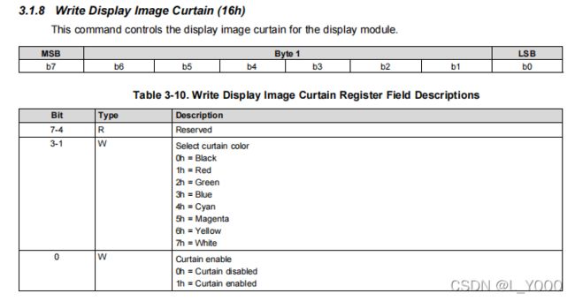
1.230EVM主控投影的芯片是DLP3436,官网下载的手册有记录每一个寄存器的功能,对应python中的函数。比如WriteDisplayImageCurtain ,在手册中是
所以我想要实现 python中的Summary = WriteDisplayImageCurtain(1,Color.Black),只需要将0X01写入0x16h寄存器即可。此函数只需写入8位,所以len=1。
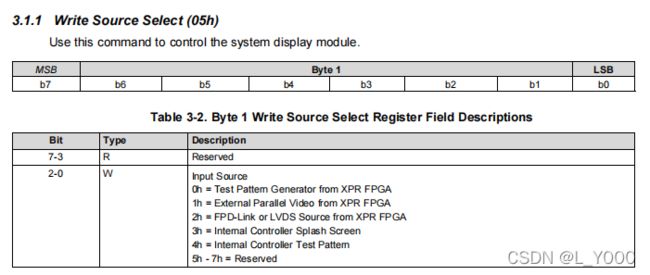
2.有些函数是需要写入16位,比如WriteSourceSelect,在手册中看不出来
可在python中WriteSourceSelect具体函数中看出
setbits写了两次
def WriteSourceSelect(Source,  ExternalCalibrationEnable):
    "Selects the source of the image to be displayed."
    global Summary
    Summary.Command = "Write Source Select"
    Summary.Successful = True
    global ProtocolData
    ProtocolData.CommandDestination = 0;
    try:
        writebytes=list(struct.pack('B',5))
        ProtocolData.OpcodeLength = 1;
        packerinit()
        value = setbits(Source.value, 3, 0)
        writebytes.extend(list(struct.pack('B',value)))
        packerinit()
        value = setbits(ExternalCalibrationEnable.value, 1, 0)
        writebytes.extend(list(struct.pack('B',value)))
        _writecommand(writebytes, ProtocolData)
    except ValueError as ve:
        print("Exception Occurred ", ve)
        Summary.Successful == False
    finally:
        return Summary
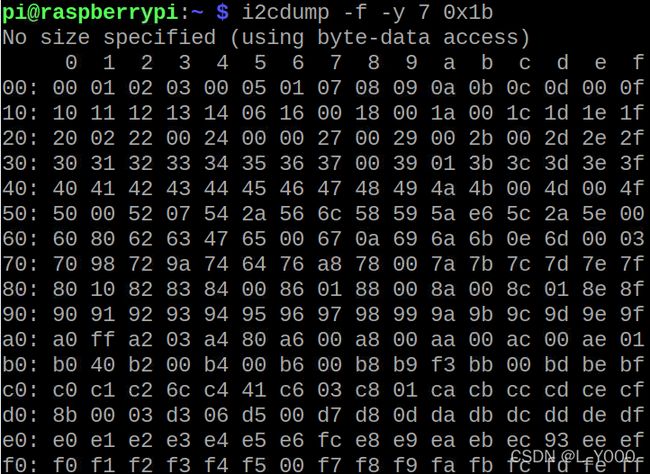
3.查看i2c总线上占用情况,可使用指令
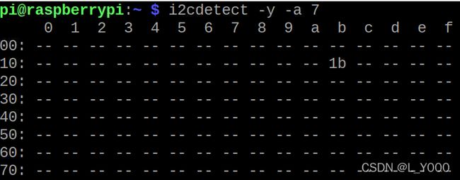
i2cdump -f -y 7 0x1b查看i2c地址,可使用指令
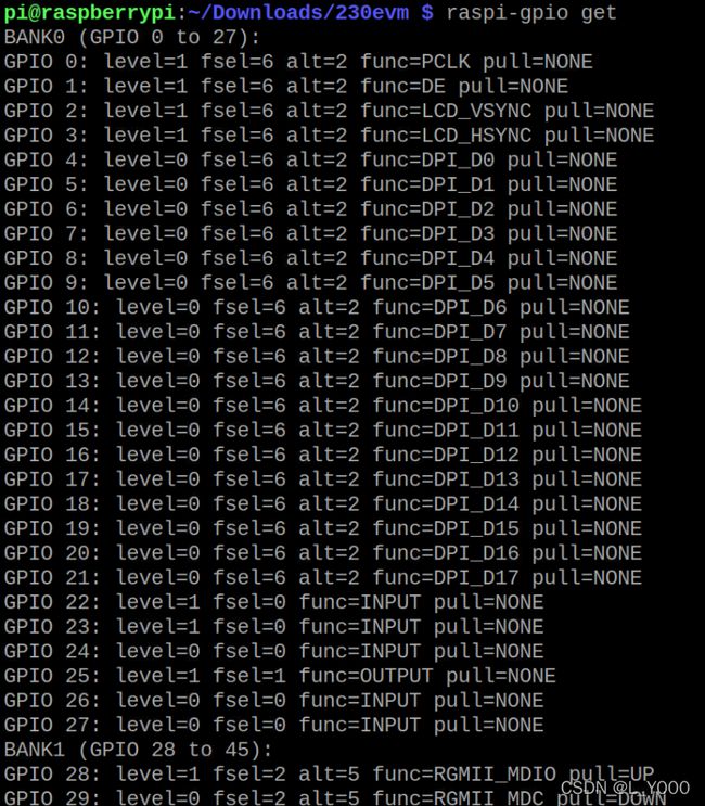
i2cdetect -y -a 74.运行程序之后,gpio引脚会发生变化,可通过以下指令查看 。
raspi-gpio get5.强制改变i2c总线上某寄存器地址,可通过如下指令。
i2cset -f -y 7 0x1b 0x16 0x01(i2c-7,地址0x1b,给0x16寄存器 写0x01 )
