计算机组成与结构综合大实验验优:16位运算器设计实验、存储器实验、控制器实验、16位CPU设计实验
综合性比较强的大实验,先是在实验室完成前面三个小实验,最后再三个结合完成最后的16位CPU的设计,需要软硬件结合一起。
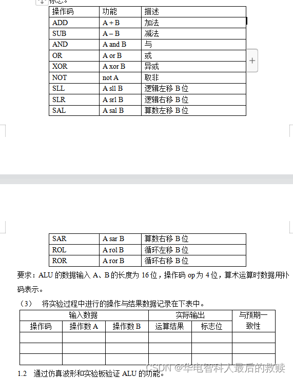
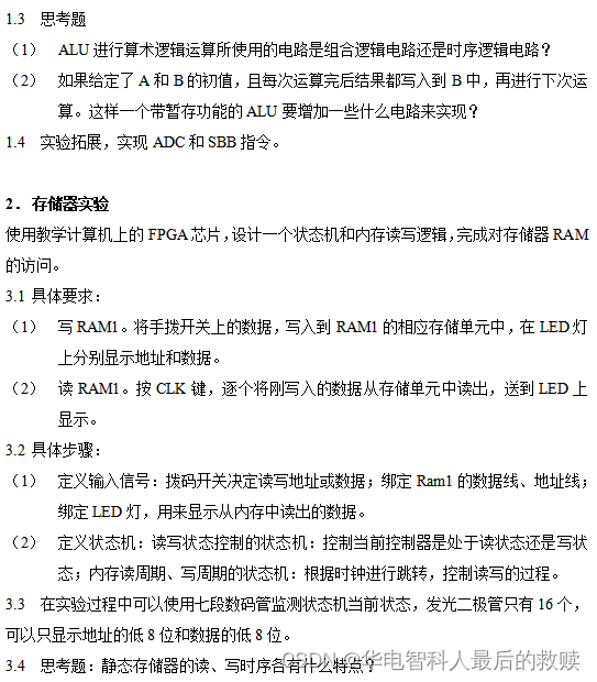


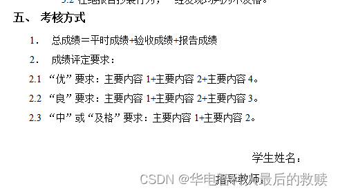
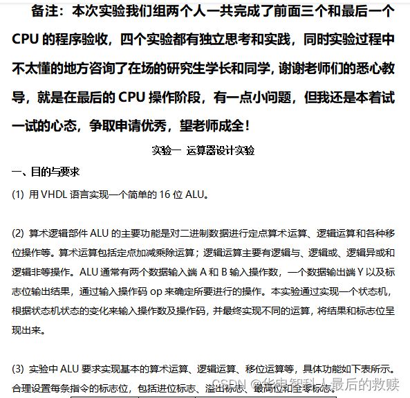

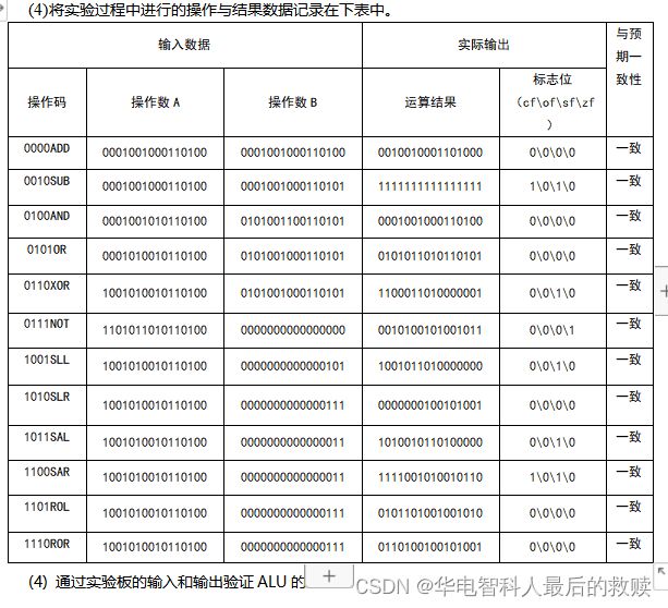

部分代码如下:
process(RST, CLK)
begin
if RST = '0' then state <= 0; a<="0000000000000000"; b<="0000000000000000"; opCode<="0000"; output <= (others=>'0'); stateCnt <= not "0000000";
	elsif CLK'event and CLK = '1' then
			case state is
				when 0 => state <= 1; a <= INPUT; stateCnt <= not "1000000";OUTPUT<=a;
				when 1 => state <= 2; b <= INPUT; stateCnt <= not "1111001";OUTPUT<=b;
				when 2 => state <= 3; opCode <= input(3 downto 0); stateCnt <= not "0100100"; OUTPUT <= input;
				when 3 => state <= 4; OUTPUT<= y; stateCnt <= not "0110000";
				when 4 => state <= 0; output<= outout; stateCnt <= not "0011001";
			end case;
		end if;
	end process;
	process(RST, opCode)
	begin
			cflag <= '0';
			oflag <= '0';
			zflag <= '0';
			sflag <= '0';
			case opCode is
			-- 加法
			when "0000"	=>	y<= a + b;
				if(y = "0000000000000000") then
					zflag <= '1';
				end if;
				if(a(15) = '1' and b(15) = '1') then
					cflag <= '1';
					if(y(15) = '0') then
						oflag <= '1';
					end if;
				end if;
				if(a(15) = '0' and b(15) = '0' and y(15) = '1') then
					oflag <= '1';
				end if;
				if(y(15) = '1') then
					sflag <= '1';
				end if;
				temp <= "1111111111111111" - a;
				if(b > temp) then
					cflag <= '1';
				end if;
			-- 减法
			when "0001"	=>	y<= a + (not b) + 1;
				if(y(15) = '1') then
					sflag <= '1';
				end if;
				if(y = "0000000000000000") then
					zflag <= '1';
				end if;
				temp <= (not b) + 1;
				if(a(15) = '1' and temp(15) = '1') then
					cflag <= '1';
					if(y(15) = '0') then
						oflag <= '1';
					end if;
				end if;
				if(a(15) = '0' and temp(15) = '0' and y(15) = '1') then
					oflag <= '1';
				end if;
				if(a < b) then
					cflag <= '1';
				end if;
			-- 加减,逻辑与,或,亦或,非,逻辑、循环、算数
			when "0010" => y<= a and b;
				if(y(15) = '1') then
					sflag <= '1';
				end if;
				if(y = "0000000000000000") then
					zflag <= '1';
				end if;
			when "0011" => y<= a or b;
				if(y(15) = '1') then
					sflag <= '1';
				end if;
				if(y = "0000000000000000") then
					zflag <= '1';
				end if;
			when "0100" => y<= a xor b;
				if(y(15) = '1') then
					sflag <= '1';
				end if;
				if(y = "0000000000000000") then
					zflag <= '1';
				end if;
			when "0101" => y<= not a;
				if(y(15) = '1') then
					sflag <= '1';
				end if;
				if(y = "0000000000000000") then
					zflag <= '1';
				end if;
			-- 逻辑
	when "0110" => y<= to_stdlogicvector(to_bitvector(a) sll conv_integer(b));
	when "0111" => y<= to_stdlogicvector(to_bitvector(a) srl conv_integer(b));
			-- 算数
	when "1000" => y<= to_stdlogicvector(to_bitvector(a) sll conv_integer(b));
when "1001" => y<= to_stdlogicvector(to_bitvector(a) sra conv_integer(b));
			-- 循环
when "1010" => y<= to_stdlogicvector(to_bitvector(a) rol conv_integer(b));
when "1011" => y<= to_stdlogicvector(to_bitvector(a) ror conv_integer(b));
	--		when "0010"	=>	y<= a + b + Cin;
	--		when "0011"	=>	y<= a - b - Cin;

3.实验拓展(实现ADC和SBB指令,已经验收通过)
	-- ADC(带进位加)
初始进位,A异或B异或C(三个里面有奇数个1则为1),向高一位的进位,AB或AC或BC(至少有两个1则有进位)
			when "1100"	=>	y<= a + b+cflag;
				if(y = "0000000000000000") then
					zflag <= '1';
				end if;
				if(a(15) = '1' and b(15) = '1') then
					cflag <= '1';
					if(y(15) = '0') then
						oflag <= '1';
					end if;
				end if;
				if(a(15) = '0' and b(15) = '0' and y(15) = '1') then
					oflag <= '1';
				end if;
				if(y(15) = '1') then
					sflag <= '1';
				end if;
				temp <= "1111111111111111" - a;
				if(b > temp) then
					cflag <= '1';
				end if;

	-- SBB带借位减(A-B-C)
初始借位,A异或B异或C(三个里面有奇数个1则为1),向高一位的借位,(BC均为1或BC有一个为1同时A为0就要借位即借位为1)
			when "1101"	=>	y<= a + (not b) -cflag;
				if(y(15) = '1') then
					sflag <= '1';
				end if;
				if(y = "0000000000000000") then
					zflag <= '1';
				end if;
				temp <= (not b) + 1;
				if(a(15) = '1' and temp(15) = '1') then
					cflag <= '1';
					if(y(15) = '0') then
						oflag <= '1';
					end if;
				end if;
				if(a(15) = '0' and temp(15) = '0' and y(15) = '1') then
					oflag <= '1';
				end if;
				if(a < b) then
					cflag <= '1';
				end if;
			when others=> y<="0000000000000000";
		end case;
		outout(15) <= oflag;
		outout(14) <= cflag;
		outout(13) <= zflag;
		outout(12) <= sflag;
	end process;
- 实验截图
黄色圈的地方是输入步骤显示
蓝色圈的地方是标志位和结果显示的LED灯
红色圈的地方是输入决定ALU功能的操作码的地方,以及输入计算的数据的地方。
(需要小心的是0~15是从左到右,拨上去是0,拨下来是1)

三、综合实验总结
1.实验难点
(1) 在输出标志位时,如何通过操作数和操作结果判断标志位:
(2)在判断进位标志位cFlags时,需要仔细考虑指令对标志位的影响和影响的原理,尤其是ADC指令和SBB指令,需要记录每一位的进位并利用循环结构得到最终结果和进位标志位(类似全加器原理)。
(3)在判断溢出标志位oFlags时,要灵活掌握操作数和运算结果之间符号位的变化与OF标志位的关系,以便正确设置标志位。
(4)在进行移位运算时,要将需要被移位的操作数(即A)的数据类型转换为位矢量类型后才可以移位,将移位操作数转换成整数。
2.心得体会
略
四、思考题
(1)ALU进行算术逻辑运算所使用的电路是组合逻辑电路还是时序逻辑电路?
答:组合逻辑电路,没有记忆功能,此时刻输入只取决于此时刻输出。
(2)如果给定了A和B的初值,且每次运算完后结果都写入到B中,再进行下次运算。这样一个带暂存功能的ALU要增加一些什么电路来实现?
答: 增加暂存器TMP和累加器AC。
六.部分代码展示
begin
	   process(RST,ctrl_r)
				begin
				if RST='0' then
					ctrl_state<=N;
				elsif rising_edge(ctrl_r)then
					case ctrl_state is
						when N=>
							ctrl_state<=W;
						when W=>
							ctrl_state<=R;
						when R=>
							ctrl_state<=W;
					end case;
				end if;
				end process;
			process(RST,CLK,ctrl_state)
				begin
				if RST='0' then
					tmp_data<=x"0000";
					tmp_read_addr<=x"0000";
					tmp_addr<=x"0000";
					to_light<=x"0000";
					RAM1_EN<='1';
					RAM1_OE<='0';
					RAM1_We<='0';
					address_state<=waiting;
					write_state<=waiting;
					read_state<=waiting;
				elsif rising_edge(CLK) then
					case ctrl_state is
							when N=>
							ADDR<=Input_data;
										SEG <=  not"1000000";
										tmp_addr<=Input_data;
										tmp_read_addr<=Input_data;
							when W=>
							case write_state is
								when waiting =>
									address_state<=waiting ;
									write_state<=start;
									read_state<=waiting;
									SEG <=  not"1000000";
								when start=>
									--tmp_data<=Input_data;
									ADDR<=tmp_addr;
									DATA<=Input_data;
									RAM1_EN<='0';
									RAM1_OE<='1';
									RAM1_We<='0';
									SEG<=not"1111001";
									write_state<=over;
								when over=>
								    write_state<=waiting;
									tmp_addr<=tmp_addr+1;
								    SEG <= not "0100100";
							end case;
							when r=>
							case read_state is
								when waiting=>
								   address_state<=waiting;
									read_state<=start;
									write_state<=waiting;
									SEG <=  not"1000000";
								when start=>
								   RAM1_EN<='0';
									RAM1_OE<='1';
									RAM1_We<='1';
									ADDR<=tmp_read_addr;
									DATA<=(others=>'Z');

									read_state<=read;
									SEG<=not"1111001";
								when read=>
								    RAM1_OE<='0';

									 RAM1_We<='1';
									to_light<=DATA;
								    SEG <=not "0100100";
									 read_state<=over;
								when over=>
								    SEG <= not"0110000";
									 read_state<=waiting;
									 tmp_read_addr<=tmp_read_addr+1;
							end case;
					end case;

				end if;
				dbc<='1';
				end process;
				light<=to_light;
				end Behavioral;
三、综合实验总结
1.实验难点
略
2.心得体会
略
四、思考题
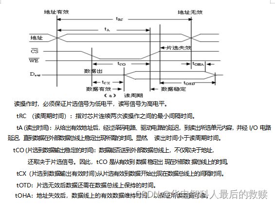
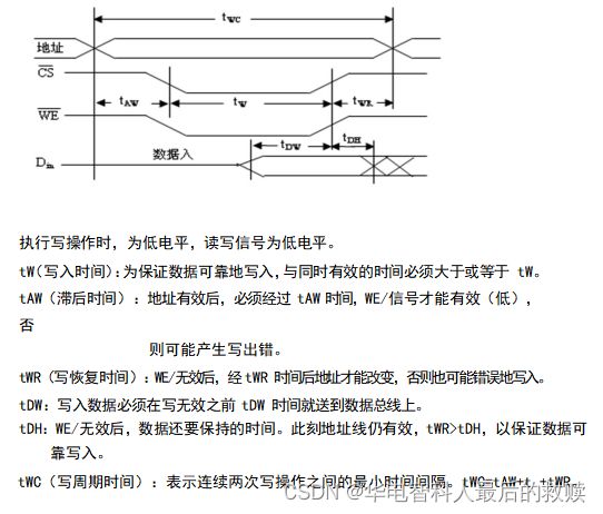
静态存储器的读、写时序各有什么特点?
3.部分代码展示
architecture Behavioral of unit is
	signal bzero : std_logic;(布尔)------------------------
	type shower_state is (PC,ALU,Mem,Reg);--------枚举类型,有四种状态---计数,加法器,内存,寄存器
	signal shower : shower_state;--------------------
	type controler_state is
	(instruction_fetch,decode,execute,mem_control,write_reg);
	signal state : controler_state;
	signal PCWrite : std_logic;-------------------是否改写PC
	signal PCWriteCond : std_logic;--------------------转移指令的条件
	signal PCSource : std_logic;------------------------新的PC来源选择
	signal ALUOp : std_logic_vector(1 downto 0);-----ALU运算功能选择
	signal ALUSrcA : std_logic;---------------------------ALU源操作数A的选择
	signal ALUSrcB : std_logic_vector(1 downto 0);
	signal MemRead : std_logic;--------------------------是否读寄存器
	signal MemWrite : std_logic;--------------------------是否写寄存器
	signal IRWrite : std_logic;-----------------------------写IR
	signal MemtoReg : std_logic_vector(1 downto 0);---写入寄存器堆的数据来源选择
	signal RegWrite : std_logic_vector(2 downto 0);------写寄存器控制
	signal RegDst : std_logic_vector(1 downto 0);--------选择目的寄存器
	signal IorD : std_logic;-----------------存储器地址来源
	signal tmpb_zero : std_logic;
	signal tmp_light : std_logic_vector(15 downto 0);
begin
light <= tmp_light;----灯
process(clk,rst,showCtrl)---------按钮
begin
	if rst='0' then
		shower<=PC;
	elsif rising_edge(showCtrl) then-----按
		case shower is    -----跳转四个状态
			when PC=>
				shower<=ALU;
			when ALU=>
				shower<=Mem;
			when Mem=>
				shower<=Reg;
			when Reg=>
				shower<=PC;
		end case;
	end if;
end process;
process(clk0,rst,state)
begin
	if rst='0' then
		tmp_light<=x"0000";
	elsif rising_edge(clk0) then
		case shower is
			when PC=>
				tmp_light(15 downto 0)<=x"0000";
				tmp_light(15)<=PCWrite;
				tmp_light(11)<=PCSource;
				tmp_light(7)<=PCWriteCond;
			when ALU=>
				tmp_light(15 downto 0)<=x"0000";
				tmp_light(15 downto 14)<=ALUOp;
				tmp_light(11)<=ALUSrcA;
				tmp_light(7 downto 6)<=ALUSrcB;
			when Mem=>
				tmp_light(15 downto 0)<=x"0000";
				tmp_light(15)<=MemRead;
				tmp_light(11)<=MemWrite;
				tmp_light(7)<=IRWrite;
				tmp_light(3 downto 2)<=MemtoReg;
			when Reg=>
				tmp_light(15 downto 0)<=x"0000";
				tmp_light(15 downto 13)<=RegWrite;
				tmp_light(11 downto 10)<=RegDst;
				tmp_light(7)<=IorD;
		end case;
	end if;
end process;
process(rst,bzero_Ctrl)
begin
		if rst = '0' then
			bzero<='0';
		elsif rising_edge (bzero_Ctrl) then
			if bzero <= '0' then
				bzero <= '1';
				tmpb_zero<='0';
			elsif bzero = '1' then
				tmpb_zero<='1';
				bzero<='0';
			end if;
		end if;
end process;
process (bzero)
begin
	if bzero = '1' then
		PCWriteCond<='1';
	elsif bzero = '0' then
		PCWriteCond<='0';
	end if;
end process;
process (rst,clk)
begin
	if(rst = '0') then
		state<=instruction_fetch;
		IorD<='0';
		IRWrite<='0';
		MemRead<='0';
		MemWrite<='0';
		MemtoReg<="00";
		ALUOp<="00";
		ALUSrcA<='0';
		ALUSrcB<="00";
		PCWrite<='0';
		PCSource<='0';
		RegDst<="00";
		RegWrite<="000";
		elsif rising_edge (clk) then
			case state is
				when instruction_fetch=>--------------取指
					MemRead<='1';
					ALUSrcA<='0';
					IorD<='0';
					ALUSrcB<="01";
					ALUOp<="00";
					PCWrite<='1';
					PCSource<='0';
					IRWrite<='1';
					RegWrite<="000";
					state<=decode;
				when decode=>----------------译码
					IRWrite<='0';
					MemRead<='0';
					PCWrite<='0';
					ALUSrcA<='0';
					ALUSrcB<="10";
					ALUOp<="00";
					state<=execute;
				when execute=>---------------执行
					case instructions(15 downto 11) is
						when "00100" =>
							ALUSrcA<='1';
							ALUOp<="10";
							PCSource<='1';
							state<=instruction_fetch;
						when "10011"=>
							ALUSrcA<='1';
							ALUSrcB<="10";
							ALUOp<="00";
							state<=mem_control;
						when "11011"=>
							ALUSrcA<='1';
							ALUSrcB<="10";
							ALUOp<="00";
							state<=mem_control;
						when "11100" =>
							case instructions (1 downto 0) is
								when "01" =>    -----addu
									ALUSrcA<='1';
									ALUSrcB<="00";
									ALUOp<="00";
								when "11" =>     -----subu
									ALUSrcA<='1';
									ALUSrcB<="00";
									ALUOp<="01";
								when others =>
									null;
							end case;
							state <=write_reg;
						when "11101" =>
							case instructions(4 downto 0) is
								when "01101" =>
									ALUSrcA<='1';
									ALUSrcB<="00";
									ALUOp<="10";
									state<=write_reg;
								when "00000" =>
									case instructions(7 downto 5) is
										when "000"=>
											ALUSrcA<='1';
											ALUOp<="10";
											PCWrite<= '1';
											PCSource <= '0';
											state<= instruction_fetch;
										when others=>
											null;
									end case;
								when others =>
									null;
							end case;
							when others=>
								null;
						end case;
					when mem_control =>---------------访存
						PCWrite<= '0';
						RegWrite<="000";
						case instructions(15 downto 11) is
							when "10011" =>
								MemRead <= '1';
								IorD <= '1';
								state <= write_reg;
							when "11011" =>
								MemWrite <= '1';
								IorD <= '1';
								state <= write_reg;
							when others =>
								null;
						end case;
					when write_reg=>----------------写入
						Memwrite <= '0';
						MemRead <= '0';
						case instructions (15 downto 11) is
							when "10011" =>
							RegDst <= "10";
							RegWrite <= "001";
							MemtoReg <= "01";
						when "11011" =>
							MemWrite <= '0';
							IorD <= '0';
						when "11100" =>
							case instructions (1 downto 0) is
								when "01" =>
									RegDst<= "01";
									RegWrite<= "001";
									MemtoReg <= "00";
								when "11" =>
									RegDst <="01";
									RegWrite<= "001";
									MemtoReg <= "00";
								when others =>
									null;
							end case;
						when "11101" =>
							case instructions (4 downto 0) is
								when "01101"=>
									RegDst <="00";
									RegWrite<= "001";
									MemtoReg <= "00";
								when others =>
									null;
							end case;
						when others=>
							null;
					end case;
					state <= instruction_fetch;
				end case;
			end if;
		end process;
end Behavioral;
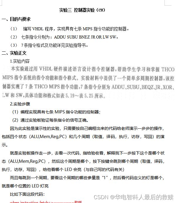
三.执行阶段实现的七条指令
七条指令分别为:ADDU SUBU BNEZ JR OR LW SW。
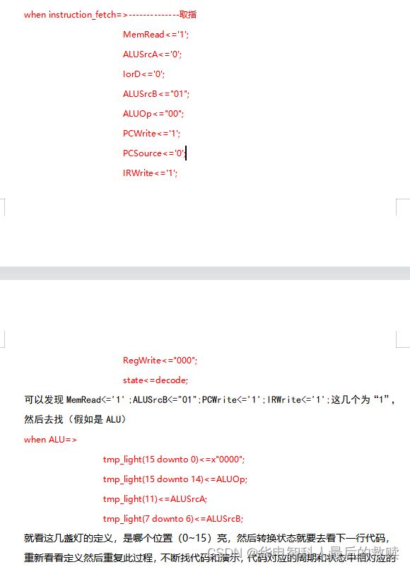
前面演示了取值,译码,到执行的时候,需要参考实验书上的131页到133页的七条指令格式的设计,这时候对应的代码会有指令的指示跳转到各自的指令执行的地方,LED灯会有各自的位置亮起。至于指令的数据通路和解释,将在下一个实验CPU中给出。
下面给出实验时候执行阶段手写的指令: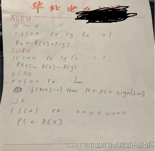

四.实验截图
红色部分是演示时候LED灯亮的位置
黄色部分是执行阶段输入的指令代表的数字
蓝色部分三个按钮有重置,跳转状态(ALU,Mem,Reg,PC),跳转周期(取值,译码,执行,访存,写回)的功能,即CLK,RST和右边第一个红色小按钮。
实验四 16位CPU设计实验
一、目的与要求
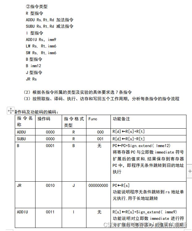
实现一个基于MIPS指令集的CPU,数据总线16位,地址总线16位,具有8个16位的通用寄存器。指令包括访存指令(如LW,SW),传送指令(如LI,MOVE),算术运算指令(如ADDU,SUBU),逻辑运算指令(NOT,OR),移位运算指令(如SLL),具体指令见实验指导书P23-P32。
具体要求:
(1)完成7条指令,必须包括访存指令LW和SW,其余每类指令最多2条。
(2)按照取指、译码、执行、访存和写回五个工作周期,分析每条指令的指令流程。
(3)根据指令流程,设计每条指令的CPU数据通路,定义涉及的所有微操作控制信号。然后逐一合并数据通路,说明增加或减少处理器功能部件的理由。给出控制器的完整设计过程。
(4)编写VHDL程序实现CPU,并通过实验板验证。
二、实验正文
1.实验内容
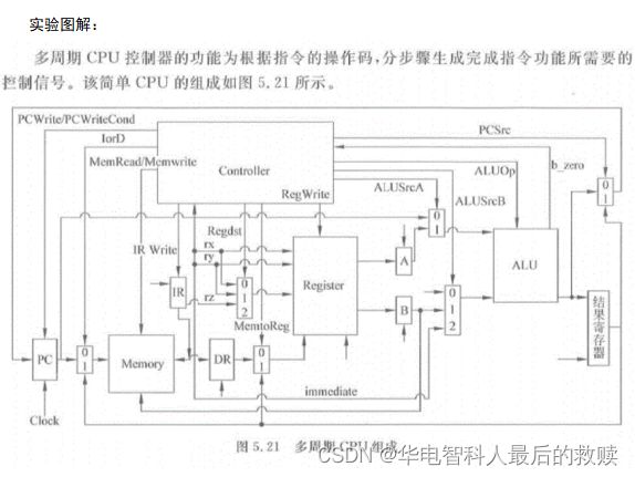
(1)实现一个基于MIPS指令集的多周期CPU
(2)设计完成7条指令,必须包括访存指令LW和SW,其余每类指令最多2条
(3)按照取指、译码、执行、访存和写回五个工作周期,分析每条指令的指令流程
(4)根据指令流程,设计每条指令的CPU数据通路,定义涉及的所有微操作控制信号。然后逐一合并数据通路,说明增加或减少处理器功能部件的理由。给出控制器的完整设计过程。
(5)编写VHDL程序实现CPU,并通过实验板验证。
(6)给出完整的设计报告,包括基本部件设计,如寄存器组、特殊寄存器、多路选择器等;每一条指令的数据通路图,以及CPU总数据通路图;控制器的设计等。
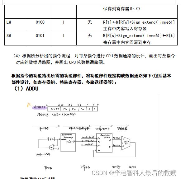
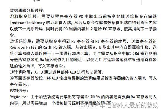
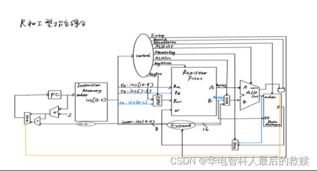
数据通路分析过程:
①取指令阶段:需要从程序寄存器PC中取出当前指令地址送给指令存储器InstructionMemory的地址输入端,然后从指令存储器数据输出端口得到指令内容以便下一周期译码,同时要将PC当前内容加2送给PC寄存器,使其指向下一条指令。
②译码阶段:需要从指令中得到Rs寄存器和Rt寄存器的编号,送给寄存器组RegisterFiles的Ra和Rb输入端,从输出端A、B取出其中内容即源操作数,送给运算器输入端以便于下一步进行减法运算,同时需要从指令中取出Rd寄存器编号送给寄存器组Rw输入端作为目的地址,以便之后将运算器运算结果送给寄存器组的输入端W,写入寄存器Rd。
③计算阶段:A、B通过运算部件ALU进行减法运算。
④写回寄存器阶段:将ALU输出端得到的运算结果送给寄存器组的输入端W,写入寄存器Rd。
控制信号:
RegWrite:由于加法功能需要读出寄存器Ra和Rb的内容还需要向Rw寄存器写入内容,所以需要增加一个控制信号控制寄存器组的读/写。
ALUop:由于ALU的功能有多种,故增加一个控制信号控制ALU功能选择。
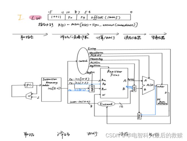
(3)LW
①取指令阶段:需要从程序寄存器PC中取出当前指令地址送给指令存储器InstructionMemory的地址输入端,然后从指令存储器数据输出端口得到指令内容以便下一周期译码,同时将PC加2送给PC,指向下一条指令。
②译码阶段:需要从指令中的第11位到第9位取出Rs寄存器编号送给寄存器组Ra输入端,从输出端A取出Rs寄存器内容送给运算器A输入端,第5位到第0位取出6位立即数经过扩展送给运算器B输入端,同时还要将指令第8位到第6位送给Rw输入端作为目的寄存器编号。
③计算阶段:A、B输入的内容送给运算器进行加法运算。
④读存储器:ALU输出内容送给数据存储器地址输入端addr。
⑤写回寄存器:数据存储器数据输出端D送给寄存器组数据写入端W,根据Rw中存放的Rt寄存器编号,将数据写入Rt寄存器。
控制信号:
ALUop:控制选择ALU功能为加法。
ALUsrcB:控制选择运算器B输入端的内容来源,本指令中来源于指令低6位扩展到16位后的立即数。
RegWrite:控制寄存器组的读出和写入。
RegDsrc:控制选择寄存器组Rw输入端的来源,本指令中应选择指令8到6位作为寄存器编号。
Jump、PCsource:控制下一条指令的转移。
RWmem:控制数据存储器的读出和写入。
Wsrc:控制选择写入寄存器的数据来源,本指令来源于数据存储器输出数据。
(4)SW
数据通路分析过程:
①取指令阶段:需要从程序寄存器PC中取出当前指令地址送给指令存储器InstructionMemory的地址输入端,然后从指令存储器数据输出端口得到指令内容以便下一周期译码,同时将PC加2送给PC,指向下一条指令。
②译码阶段:需要从指令中的第11位到第9位取出Rs寄存器编号送给寄存器组Ra输入端,从输出端A取出Rs寄存器内容送给运算器A输入端,第5位到第0位取出6位立即数经过扩展送给运算器B输入端,同时还要将指令第8位到第6位送给Rb输入端作为输入数据寄存器编号。
③计算阶段:运算器对A、B输入的内容进行加法运算,运算后结果为目的地址需要送给数据存储器地址端addr。
④读寄存器:寄存器组B输出端内容输入数据,将其送给数据存储器数据输入端W。
⑤写回存储器:将数据存储器输入端W的数据写入目的地址addr。
控制信号:
ALUop:控制选择ALU功能为加法。
ALUsrcB:控制选择运算器B输入端的内容来源,本指令中来源于指令低6位扩展到16位后的立即数。
RegWrite:控制寄存器组的读出和写入。
Jump、PCsource:控制下一条指令的转移。
RWmem:控制数据存储器的读出和写入。
Wsrc:控制选择写入寄存器的数据来源,本指令来源于数据存储器输出数据。

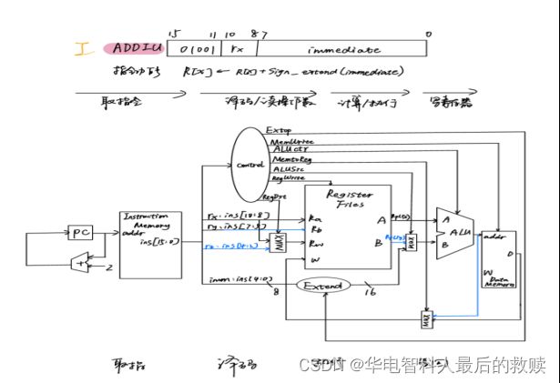
(5)ADDIU
数据通路分析过程:
①取指令阶段:需要从程序寄存器PC中取出当前指令地址送给指令存储器InstructionMemory的地址输入端,然后从指令存储器数据输出端口得到指令内容以便下一周期译码,同时将PC加2送给PC,指向下一条指令。
②译码阶段:需要从指令中的第11位到第9位取出Rs寄存器编号送给寄存器组Ra输入端,从输出端A取出Rs寄存器内容送给运算器A输入端,第11位到第9位取出Rs寄存器编号还要送给Rw输入端作为运算后的目的寄存器编号,取出指令的8到0位送给运算器B输入端,。
③计算阶段:A、B输入的内容送给运算器进行加法运算。
④写回阶段:ALU输出内容送给寄存器组W输入端写回Rw所存的编号的寄存器。
控制信号:
ALUop:控制选择ALU功能为加法。
ALUsrcB:控制选择运算器B输入端的内容来源,本指令中来源于指令低9位扩展到16位后的立即数。
RegWrite:控制寄存器组的读出和写入。
RegDsrc:控制选择寄存器组Rw输入端的来源,本指令中应选择指令11到9位作为寄存器编号。
Jump、PCsource:控制下一条指令的转移。
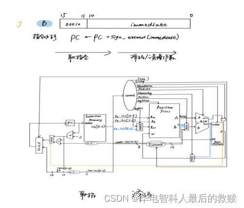
数据通路分析过程:
①取指令阶段:需要从程序寄存器PC中取出当前指令地址送给指令存储器InstructionMemory的地址输入端,然后从指令存储器数据输出端口得到指令内容以便下一周期译码。
②译码阶段:需要从指令中的低12位扩展成16位与当前PC内容相加送回PC。
控制信号:
Jump:由于PC的值和当前执行指令有关,故增加一个控制信号Jump通过一个多路选择器控制PC的选择。
(7)JR

数据通路分析过程:
①取指令阶段:需要从程序寄存器PC中取出当前指令地址送给指令存储器InstructionMemory的地址输入端,然后从指令存储器数据输出端口得到指令内容以便下一周期译码。
②译码阶段:需要从指令中的第11位到第9位取出Rs寄存器编号送给寄存器组Ra输入端,从输出端A取出Rs寄存器内容以便下一步根据指令功能通过运算器运算。
③计算阶段:寄存器取出的内容送给ALU输入端A,通过ALUop控制信号选择直接输出源操作数A的功能。
④写回阶段:ALU输出内容送给PC。
控制信号:
RegWrite:由于需要将读出Rs寄存器内容,所以需要一个寄存器读信号,将内容从寄存器组输出端口A输出。
ALUop:此指令运算器需要新的功能,故用ALUop信号控制运算器功能选择,这条指令中应该选择输出Y=A。
PCsource:PC的内容又增加了新的选择,故需要一个OPsource信号通过多路选择器控制PC的输入选择。
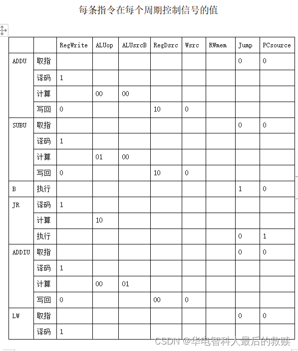
(5)根据CPU总数据通路图设计控制器:列出控制信号表格以及每条指令在每个指令周期控制信号的值,完成控制器完整设计:



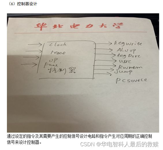
(7)部分代码展示
process(RST,showCtrl) -----状态转换
begin
if RST = '0' then
State_show <= PC;
stateCnt_L <= "0111001";
elsif showCtrl'event and showCtrl = '1' then
case State_show is
when PC =>
stateCnt_L <= "0000110";
State_show <= ALU;
when ALU =>
stateCnt_L <= "1011011";
State_show <= M;
when M =>
stateCnt_L <= "1001111";
State_show <= REG;
when REG =>
stateCnt_L <= "1100110";
State_show <= PC;
end case;
end if;
end process;
......
when decode =>
stateCnt_R <= "1011011";
AluSrcA <= '0';
ALUSrcB <= "10";
ALUOp <= "00";
MemRead <= '0';
IRWrite <= '0';
PcWrite <= '0';
CU_state <= execute;
case instruction(15 downto 11) is
when "11100" =>
rx <= instruction(10 downto 8);
ry <= instruction(7 downto 5);
rz <= instruction(4 downto 2);
when "00100" => --BEQZ
rx <= instruction(10 downto 8);
IMD <= instruction(7 downto 0);
when "11101" =>
case instruction(4 downto 0) is
when "00000" => --JR
rx <= instruction(10 downto 8);
when "01110" => --XOR
rx <= instruction(10 downto 8);
ry <= instruction(7 downto 5);
when others =>
null;
end case;
when "10011" => --LW
rx <= instruction(10 downto 8);
ry <= instruction(7 downto 5);
im <= instruction(4 downto 0);
when "11011" => --SW
rx <= instruction(10 downto 8);
ry <= instruction(7 downto 5);
im <= instruction(4 downto 0);
when others =>
null;
end case;
when execute =>
stateCnt_R <= "1001111";
control_state <= 0;
case instruction(15 downto 11) is
when "11100" =>
if instruction(1 downto 0) = "01" then --ADDU
ALUSrcA <= '1';
ALUSrcB <= "00";
ALUOp <= "00";
elsif instruction(1 downto 0) = "11" then --SUBU
ALUSrcA <= '1';
ALUSrcB <= "00";
ALUOp <= "01";
end if;
CU_state <= write_reg;
when "00100" => --BEQZ
ALUSrcA <= '1';
ALUOp <= "10";
PCSource <= '1';
CU_state <= instruction_fetch;
when "11101" =>
case instruction(4 downto 0) is
when "00000" => --JR
ALUSrcA <= '1';
ALUOp <= "10";
PcWrite <= '1';
PCSource <= '0';
CU_state <= instruction_fetch;
when "01110" => --XOR
ALUSrcA <= '1';
ALUSrcB <= "00";
ALUOp <= "10";
CU_state <= write_reg;
when others =>
null;
end case;
when "10011" => --LW
ALUSrcA <= '1';
ALUSrcB <= "10";
ALUOp <= "00";
CU_state <= write_reg;
when "11011" => --SW
ALUSrcA <= '1';
ALUSrcB <= "10";
ALUOp <= "00";
CU_state <= write_reg;
when others =>
null;
end case;
when mem_control =>
stateCnt_R <= "1100110";
case instruction(15 downto 11) is
when "10011" => --LW
RegWrite <= "000";
MemRead <= '1';
IorD <= '1';
PcWrite <= '0';
case control_state is
when 2 =>
RAM1_EN <= '0';
RAM1_OE <= '1';
RAM1_WE <= '1';
DATA(4 downto 0) <= DATA(4 downto 0) + im;
tmp_read_addr <= DATA;
CU_state <= mem_control;
control_state <= 3;
when 3 =>
ADDR <= tmp_read_addr;
DATA <= (others=>'Z');
RAM1_OE<='0';
RAM1_WE<='1';
CU_state <= write_reg;
control_state <= 4;
when others =>
null;
end case;
when "11011" => --SW
RegWrite <= "000";
MemWrite <= '1';
IorD <= '1';
PcWrite <= '0';
case control_state is
when 4 =>
RAM1_EN <= '0';
RAM1_OE <= '1';
RAM1_WE <= '1';
DATA(4 downto 0) <= DATA(4 downto 0) + im;
tmp_addr <= DATA;
CU_state <= mem_control;
control_state <= 5;
when 5 =>
ADDR <= tmp_addr;
DATA <= tmp_data;
RAM1_WE<='0';
RAM1_OE<='1';
CU_state <= write_reg;
control_state <= 0;
when others =>
null;
end case;
when others =>
null;
end case;
when write_reg =>
stateCnt_R <= "1101101";
case instruction(15 downto 11) is
when "11100" =>
case instruction(1 downto 0) is
when "01" => --ADDU
RegDst <= "01";
RegWrite <= "001";
MemtoReg <= "00";
MemRead <= '0';
MemWrite <= '0';
case control_state is
when 0 =>
RAM1_EN <= '0';
RAM1_OE <= '1';
RAM1_WE <= '1';
tmp_addr1 <= "0000000000000000";
tmp_read_addr1 <="0000000000000000";
tmp_read_addr1(2 downto 0) <= rx;
CU_state <= write_reg;
control_state <= 1;
when 1 =>
ADDR <= tmp_read_addr1;
DATA <= (others=>'Z');
RAM1_OE<='0';
RAM1_WE<='1';
CU_state <= write_reg;
control_state <= 2;
when 2 =>
RAM1_EN <= '0';
RAM1_OE <= '1';
RAM1_WE <= '1';
tmp_data1 <= DATA;
tmp_read_addr1<="0000000000000000";
tmp_read_addr1(2 downto 0) <= ry;
CU_state <= write_reg;
control_state <= 3;
when 3 =>
ADDR <= tmp_read_addr1;
DATA <= (others=>'Z');
RAM1_OE<='0';
RAM1_WE<='1';
CU_state <= write_reg;
control_state <= 4;
when 4 =>
RAM1_EN <= '0';
RAM1_OE <= '1';
RAM1_WE <= '1';
tmp_data1 <= DATA + tmp_data1;
tmp_addr1(2 downto 0) <= rz;
CU_state <= write_reg;
control_state <= 5;
when 5 =>
ADDR <= tmp_addr1;
DATA <= tmp_data1;
RAM1_WE<='0';
RAM1_OE<='1';
CU_state<=instruction_fetch;
control_state <= 0;
when others =>
null;
end case;
when "11" => --SUBU
RegDst <= "01";
RegWrite <= "001";
MemtoReg <= "00";
MemRead <= '0';
MemWrite <= '0';
case control_state is
when 0 =>
RAM1_EN <= '0';
RAM1_OE <= '1';
RAM1_WE <= '1';
tmp_addr<="0000000000000000";
tmp_read_addr<="0000000000000000";
tmp_read_addr(2 downto 0) <= rx;
CU_state <= write_reg;
control_state <= 1;
when 1 =>
ADDR <= tmp_read_addr;
DATA <= (others=>'Z');
RAM1_OE<='0';
RAM1_WE<='1';
CU_state <= write_reg;
control_state <= 2;
when 2 =>
RAM1_EN <= '0';
RAM1_OE <= '1';
RAM1_WE <= '1';
tmp_data <= DATA;
tmp_read_addr<="0000000000000000";
tmp_read_addr(2 downto 0) <= ry;
CU_state <= write_reg;
control_state <= 3;
when 3 =>
ADDR <= tmp_read_addr;
DATA <= (others=>'Z');
RAM1_OE<='0';
RAM1_WE<='1';
CU_state <= write_reg;
control_state <= 4;
when 4 =>
RAM1_EN <= '0';
RAM1_OE <= '1';
RAM1_WE <= '1';
tmp_data <= tmp_data - DATA;
tmp_addr(2 downto 0) <= rz;
CU_state <= write_reg;
control_state <= 5;
when 5 =>
ADDR <= tmp_addr;
DATA <= tmp_data;
RAM1_WE<='0';
RAM1_OE<='1';
CU_state <=instruction_fetch;
control_state <= 0;
when others =>
null;
end case;
when others =>
null;
end case;
when "11101" => --XOR
RegDst <= "00";
RegWrite <= "001";
MemtoReg <= "00";
MemRead <= '0';
MemWrite <= '0';
case control_state is
when 0 =>
RAM1_EN <= '0';
RAM1_OE <= '1';
RAM1_WE <= '1';
tmp_addr <= "0000000000000000";
tmp_read_addr <="0000000000000000";
tmp_read_addr(2 downto 0) <= rx;
CU_state <= write_reg;
control_state <= 1;
when 1 =>
ADDR <= tmp_read_addr;
DATA <= (others=>'Z');
RAM1_OE<='0';
RAM1_WE<='1';
CU_state <= write_reg;
control_state <= 2;
when 2 =>
RAM1_EN <= '0';
RAM1_OE <= '1';
RAM1_WE <= '1';
tmp_data <= DATA;
tmp_read_addr <="0000000000000000";
tmp_read_addr(2 downto 0) <= ry;
CU_state <= write_reg;
control_state <= 3;
when 3 =>
ADDR <= tmp_read_addr;
DATA <= (others=>'Z');
RAM1_OE<='0';
RAM1_WE<='1';
CU_state <= write_reg;
control_state <= 4;
when 4 =>
RAM1_EN <= '0';
RAM1_OE <= '1';
RAM1_WE <= '1';
tmp_data <= tmp_data xor DATA;
tmp_addr(2 downto 0) <= rx;
CU_state <= write_reg;
control_state <= 5;
when 5 =>
ADDR <= tmp_addr;
DATA <= tmp_data;
RAM1_WE<='0';
RAM1_OE<='1';
CU_state <= instruction_fetch;
control_state <= 0;
when others =>
null;
end case;
when "10011" => --LW
RegDst <= "10";
RegWrite <= "001";
MemtoReg <= "01";
MemRead <= '0';
MemWrite <= '0';
case control_state is
when 0 =>
RAM1_EN <= '0';
RAM1_OE <= '1';
RAM1_WE <= '1';
tmp_addr <= "0000000000000000";
tmp_read_addr <="0000000000000000";
tmp_read_addr(2 downto 0) <= rx;
CU_state <= write_reg;
control_state <= 1;
when 1 =>
ADDR <= tmp_read_addr;
DATA <= (others=>'Z');
RAM1_OE<='0';
RAM1_WE<='1';
CU_state <= mem_control;
control_state <= 2;
when 4 =>
RAM1_EN <= '0';
RAM1_OE <= '1';
RAM1_WE <= '1';
tmp_data <= DATA;
tmp_addr(2 downto 0) <= ry;
CU_state <= write_reg;
control_state <= 5;
when 5 =>
ADDR <= tmp_addr;
DATA <= tmp_data;
RAM1_WE<='0';
RAM1_OE<='1';
CU_state <= instruction_fetch;
control_state <= 0;
when others =>
null;
end case;
when "11011" => --SW
MemRead <= '0';
MemWrite <= '0';
IorD <= '0';
case control_state is
when 0 =>
RAM1_EN <= '0';
RAM1_OE <= '1';
RAM1_WE <= '1';
tmp_addr <= "0000000000000000";
tmp_read_addr <="0000000000000000";
tmp_read_addr(2 downto 0) <= ry;
CU_state <= write_reg;
control_state <= 1;
when 1 =>
ADDR <= tmp_read_addr;
DATA <= (others=>'Z');
RAM1_OE<='0';
RAM1_WE<='1';
CU_state <= write_reg;
control_state <= 2;
when 2 =>
RAM1_EN <= '0';
RAM1_OE <= '1';
RAM1_WE <= '1';
tmp_data <= DATA;
tmp_read_addr <="0000000000000000";
tmp_read_addr(2 downto 0) <= rx;
CU_state <= write_reg;
control_state <= 3;
when 3 =>
ADDR <= tmp_read_addr;
DATA <= (others=>'Z');
RAM1_OE<='0';
RAM1_WE<='1';
CU_state <= mem_control;
control_state <= 4;
when others =>
null;
end case;
when others =>
null;
end case;
end case;
end if;
end process;
三、综合实验总结
1.实验难点
略
2.心得体会
略
四.思考题
设计完成后,给出每条指令输入后在数据通路中的执行过程。
如上面实验步骤给出来的数据通路图,七条指令的都已经给出执行过程。
XXX申请验优!


